5164ISZ データシートの表示(PDF) - Renesas Electronics
部品番号
コンポーネント説明
メーカー
5164ISZ Datasheet PDF : 17 Pages
| |||
EL5164, EL5165, EL5364
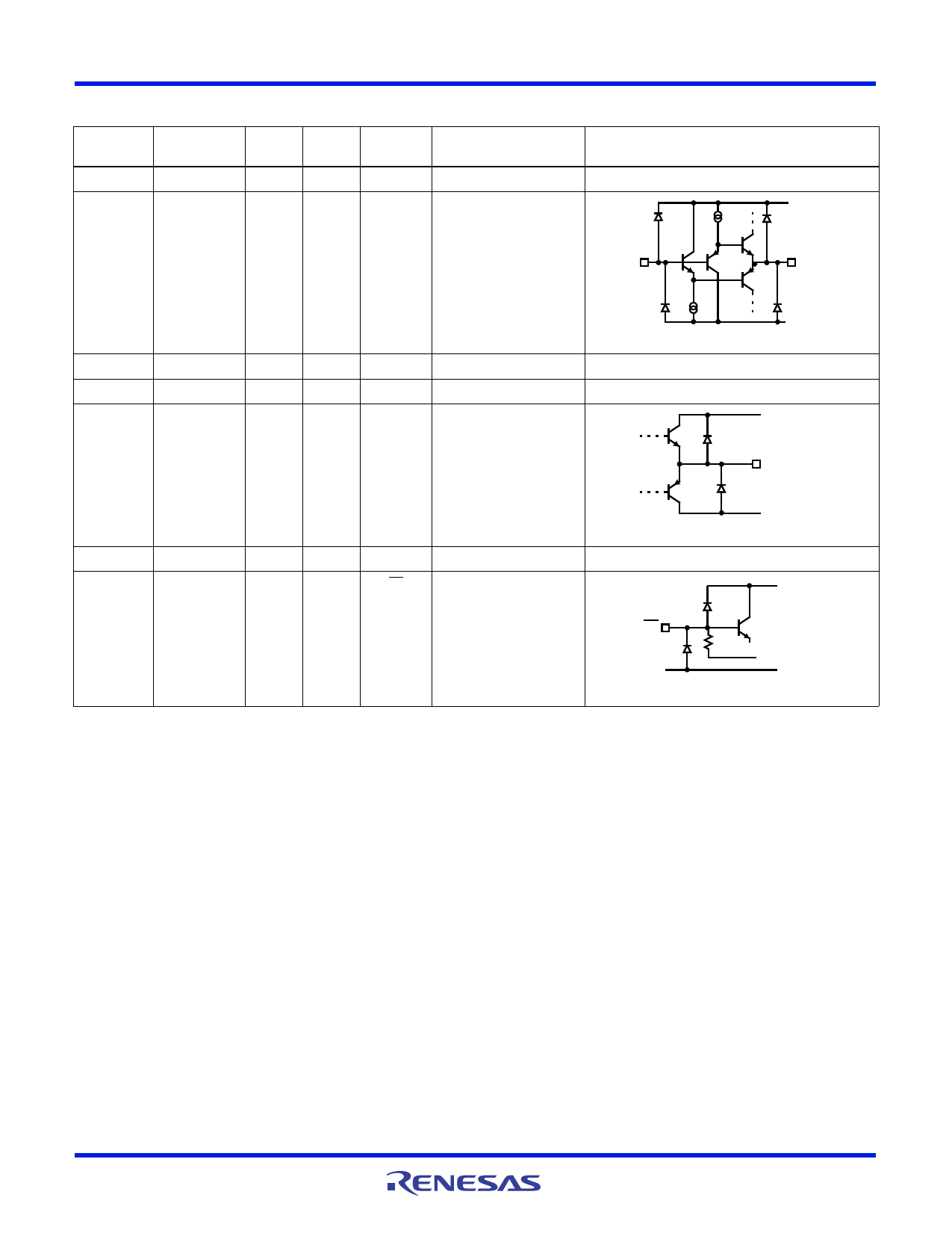
Pin Descriptions
EL5164
(8 Ld SOIC)
1, 5
2
EL5164
(6 Ld SOT-23)
4
EL5165 EL5364
Pin Name
Function
6, 11
NC
Not connected
4 9, 12, 16
IN-
Inverting input
Equivalent Circuit
VS+
IN+
IN-
VS-
CIRCUIT 1
3
3
3
1, 5, 8
IN+ Non-inverting input
(See circuit 1)
4
2
2
3
VS- Negative supply
6
1
1
10, 13,
OUT Output
VS+
15
OUT
VS-
CIRCUIT 2
7
6
5
14
VS+ Positive supply
8
5
2, 4, 7
CE
Chip enable, allowing the
pin to float or applying a
low logic level enables the
corresponding amplifier.
VS+
CE
0.5M
INTERNAL 0V
VS-
CIRCUIT 3
Applications Information
Product Description
The EL5164, EL5165, and EL5364 are current-feedback operational
amplifiers that offer a wide -3dB bandwidth of 600MHz and a low
supply current of 3.5mA per amplifier. The EL5164, EL5165, and
EL5364 work with supply voltages ranging from a single 5V to 10V
and they are also capable of swinging to within 1V of either supply
on the output. Because of their current-feedback topology, the
EL5164, EL5165, and EL5364 do not have the normal gain-
bandwidth product associated with voltage-feedback operational
amplifiers. Instead, their -3dB bandwidth remains relatively
constant as closed-loop gain increases. This combination of high
bandwidth and low power, together with aggressive pricing makes
the EL5164, EL5165, and EL5364 ideal choices for many low-
power/high-bandwidth applications such as portable, handheld, or
battery-powered equipment. For varying bandwidth needs, consider
the EL5166 and EL5167 with 1.4GHz bandwidth and an 8.5mA
supply current, or the EL5162 and EL5163 with 500MHz bandwidth
and a 1.5mA supply current. Versions include single, dual, and triple
amp configurations with 5 Ld SOT-23, 16 Ld QSOP, and 8 Ld SOIC
or 16 Ld SOIC outlines.
Power Supply Bypassing and Printed Circuit
Board Layout
As with any high frequency device, good printed circuit board
layout is necessary for optimum performance. Low impedance
ground plane construction is essential. Surface mount
components are recommended, but if leaded components are
used, lead lengths should be as short as possible. The power
supply pins must be well bypassed to reduce the risk of
oscillation. The combination of a 4.7µF tantalum capacitor in
parallel with a 0.01µF capacitor has been shown to work well
when placed at each supply pin.
For good AC performance, parasitic capacitance should be kept
to a minimum, especially at the inverting input. (See the
“Capacitance at the Inverting Input” on page 10). Even when
ground plane construction is used, it should be removed from the
area near the inverting input to minimize any stray capacitance
at that node. Carbon or Metal-Film resistors are acceptable with
the Metal-Film resistors giving slightly less peaking and
bandwidth because of additional series inductance. Use of
sockets, particularly for the SO package, should be avoided if
possible. Sockets add parasitic inductance and capacitance
which results in additional peaking and overshoot.
FN7389 Rev 9.00
January 30, 2014
Page 9 of 17
Share Link: 