TC07VOA データシートの表示(PDF) - Microchip Technology
部品番号
コンポーネント説明
メーカー
TC07VOA Datasheet PDF : 12 Pages
| |||
TC07
4.0 TYPICAL APPLICATIONS
4.1 Trip Point Programming
The resistor values required to achieve the desired trip
point temperatures on TSET and HSET are calculated
using the formula below:
Where:
RTRIP = 0.6 x T 2.13
RTRIP = Programming resistor value in Ohms
T = Desired trip point temperature in degrees Kelvin.
For example, to program the TC07 outputs to go active
at 50°C and inactive at 30°C, the RT and RH
programming resistors are calculated as follows:
RT = 0.6 x ((50 + 273.15)2.13) = 132.8kΩ
RH = 0.6 x ((30 + 273.15)2.13) = 115.9kΩ
Resistance values for TSET and HSET can be approxi-
mated using Figure 4-1. Care must be taken to ensure
the HSET programming resistor is a smaller value than
the TSET programming resistor. The temperature
programmed on HSET must be at least 5°C lower than
the temperature value programmed by TSET.
FIGURE 4-1:
250
PROGRAMMING
RESISTOR VALUES VS.
TEMPERATURE
200
150
100
50
-55 -35 -15
5
25 45 65
TEMPERATURE (°C)
85 105 125
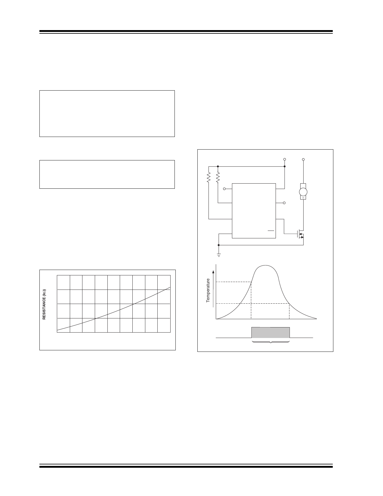
4.2 Cooling and Heating Applications
The TC07 can be used to control a DC fan as shown in
Figure 4-2. The fan turns on when the sensed temper-
ature rises above the temperature set at TSET and
remains on until the temperature falls below the tem-
perature set at HSET. The amount of “cooling"
performed by the fan is dependent on the programmed
hysteresis.
Figure 4-3 shows the TC07 acting as a heater thermo-
stat. Circuit operation is identical to that of the cooling
fan application in Figure 4-2.
FIGURE 4-2:
TC07 AS A FAN
CONTROLLER
+2.7 to 5.5V +12V
RT
RH
NC
VDD
HSET
TC07
TSET
NC
OUT
GND
OUT
+
Fan
Logic Level
MOSFET
TSET
HSET
Out
Fan "On"
DS21674C-page 4
© 2005 Microchip Technology Inc.
Share Link: 