LX432CLP データシートの表示(PDF) - Microsemi Corporation
部品番号
コンポーネント説明
メーカー
LX432CLP Datasheet PDF : 8 Pages
| |||
PRODUCT DATABOOK 1996/1997
LOW VOLTAGE ADJUSTABLE PRECISION SHUNT REGULATORS
PRODUCTION DATA SHEET
LX432
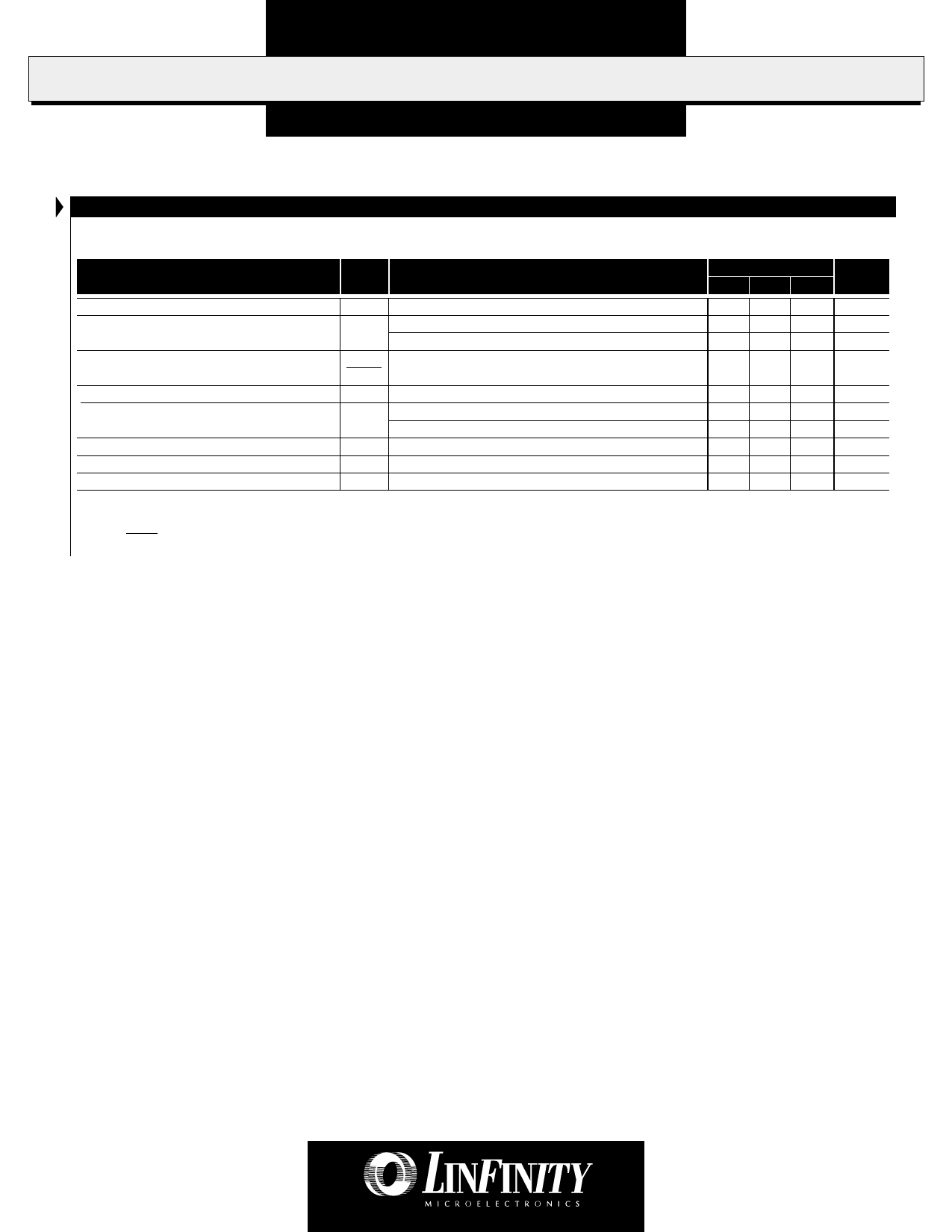
ELECTRICAL CHARACTERISTICS
(Unless otherwise specified, these specifications apply over the operating ambient temperatures for LX432C with 0°C ≤ T ≤ 70°C, and the LX432I
A
with -40°C ≤ TA ≤ 85°C.)
Parameter
Symbol
Test Conditions
LX432
Units
Min. Typ. Max.
Reference Voltage
Reference Voltage Drift (Note 2)
Ratio Of VREF Change In Cathode
Voltage Change (Note 3)
Reference Terminal Current
Reference Current Drift (Note 2)
Minimum Cathode Current For Regulation
Dynamic Impedance
Off-state Cathode Current
VREF
∆VREF
∆VREF
∆VKA
IREF
∆IREF
IK (MIN)
ZKA
IOFF
IK = 10mA, VKA = VREF, TA = 25°C
IK = 10mA, VKA = VREF, 0°C ≤ TA ≤ 70°C
IK
=
10mA,
VKA
=
VREF,
-40°C
≤
T
A
≤
85°C
IK = 10mA, VKA = VREF to 16V, TA = 25°C
IK = 10mA, VKA = VREF, TA = 25°C, R1=10kΩ, R2 = Open
IK
=
10mA,
VKA
=
VREF,
0°C
≤
T
A
≤
70°C
IK = 10mA, VKA = VREF, -40°C ≤ TA ≤ 85°C
VKA = VREF, TA = 25°C
IK = 0.1mA to 15mA, VKA = VREF, TA = 25°C
VKA = 16V, TA = 25°C
1.228 1.24 1.252
3 12
4 20
-1 -2.7
V
mV
mV
mV/V
0.1 0.5
µA
0.05 0.3
µA
0.1 0.4
µA
55 80
µA
0.2 0.4
Ω
0.004
µA
Note 2. These parameters are guaranteed by design.
Note 3. ∆VREF Ratio of change in reference input voltage
∆VKA to the change in cathode voltage.
Copyright © 1999
Rev. 1.0 9/99
3
Share Link: 