HMP8112A データシートの表示(PDF) - Harris Semiconductor
部品番号
コンポーネント説明
メーカー
HMP8112A Datasheet PDF : 40 Pages
| |||
HMP8112A
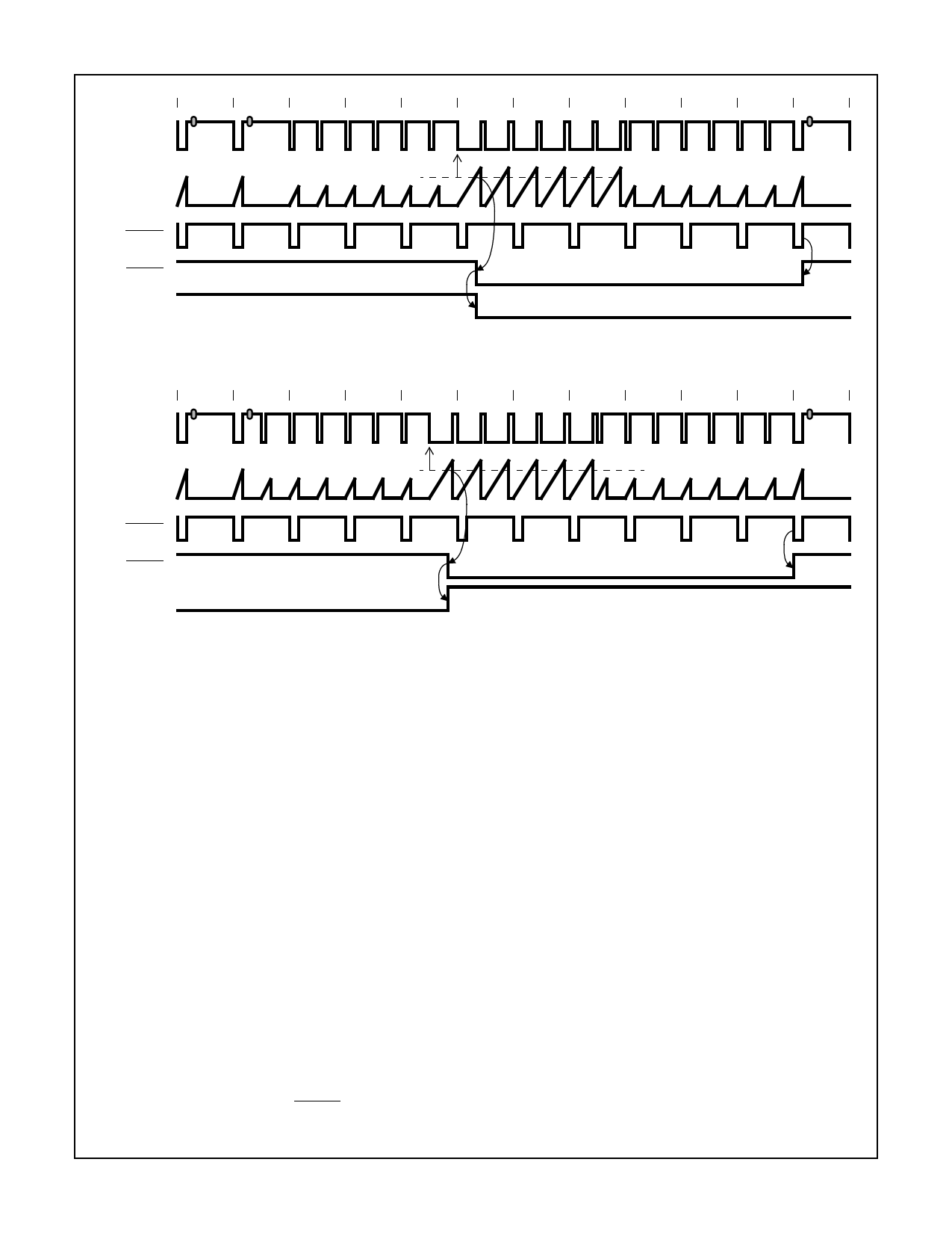
LINE #
524
525
1
2
3
4
5
6
7
8
9
10
VIDEO
INPUT
LOW TIME
COUNTER
VSYNC DETECT THRESHOLD
OV
HSYNC
VSYNC
FIELD
5
4
3
2
1
APPROX. 5.75 LINES
‘EVEN’ FIELD
‘ODD’ FIELD
FIGURE 8. VSYNC TIMING AND THE EVEN TO ODD FIELD TRANSITION
LINE #
262
263
264
265
266
267
268
269
270
271
272
273
VIDEO
INPUT
LOW TIME
COUNTER
VSYNC DETECT THRESHOLD OV
HSYNC
VSYNC
FIELD
‘ODD’ FIELD
6
5
4
3
2
1
APPROX. 6.25 LINES
‘EVEN’ FIELD
FIGURE 9. VSYNC TIMING AND THE ODD TO EVEN FIELD TRANSITION
Internal Phase Locked Loops
The HMP8112A has two independent digital phase locked
loops on chip. A chroma phase-locked loop is implemented
to maintain chroma lock for demodulation of the color chan-
nel, and a line locked phase lock loop is implemented to
maintain vertical spatial alignment. The phase locked loops
are designed to maintain lock even in the event of VCR
headswitches.
The HMP8112A can use a main crystal (CLK) of 20MHz to
30MHz. The crystal is used as a reference frequency for the
internal phase locked loops. The ratio of the crystal fre-
quency to the video standard is programmed into an internal
register for the PLLs to correctly decode video.
The HMP8112A decoder contains 2 sample rate converters
and 2 phase locked loops that lock to the incoming video.
The input sample rate converter synchronizes the digitized
video from the CLK rate to a 4xfSC rate. The chrominance is
separated from the luminance and then demodulated.
The Chroma PLL uses the CLK source as a reference fre-
quency. To initialize the Chroma PLL, the CLK to 4xfSC ratio
value must be loaded into the Chroma PLL Ratio Register
pair. A default 16-Bit Fractional Chroma PLL Ratio Value of
0x87C1 is used after a system RESET is applied. Refer to
Table 1 for example PLL Ratio values to use with the sup-
ported video standards 27MHz or 24.54MHz clocks. Using a
different CLK will require different values to be calculated per
the method shown below. The default assumes a CLK of
27MHz and NTSC as the video standard, and is calculated
as follows:
Ratio =
=
=
Register Data:
Hex Conversion:
(4 x fSC) / CLK
(4 x 3.579545MHz) / 27MHz
0.530303
Ratio * 65536
0.530303 * 65536 = 34753.94
0x87C1
The Output Sample Rate converter is locked to the horizon-
tal line frequency and is used to spatially align pixels in a
field. The LOCKED flag signals when the phase locked loop
is within a ±4 pixel range of the horizontal sync edge. When
line errors exceed that range the LOCKED flag is cleared.
In cases where VCRs are used in Pause, Fast Forward or
Fast Reverse, lines are typically dropped or added by the
VCR. In a worst case scenario a VCR line tolerance will vary
by ±8%. The standard detect logic checks the line count
against the given standard to determine an error. VCRs in
trick mode cannot cause a standard error. With an NTSC
standard VCR the number of lines in a field should not
4-8
Share Link: 