MAX703 データシートの表示(PDF) - Maxim Integrated
部品番号
コンポーネント説明
メーカー
MAX703 Datasheet PDF : 10 Pages
| |||
MAX703/MAX704
Low-Cost Microprocessor Supervisory
Circuits with Battery Backup
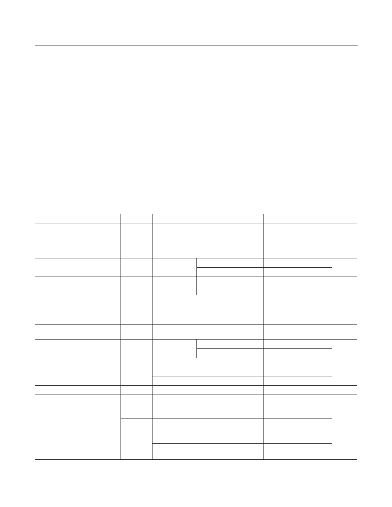
Absolute Maximum Ratings
Terminal Voltage (with respect to GND)
VCC...................................................................-0.3V to +6.0V
VBATT................................................................-0.3V to +6.0V
All Other Inputs (Note 1).......................-0.3V to (VCB + 0.3V)
Input Current
Rate-of-Rise VBATT, VCC................................................100V/μs
Operating Temperature Range
C Suffix................................................................0°C to +70°C
E Suffix.............................................................-40°C to +85°C
M Suffix..........................................................-55°C to +125°C
VCC ..............................................................................200mA
VBATT ............................................................................50mA
GND................................................................................20mA
Continuous Power Dissipation (TA = +70°C)
8-Pin PDIP (derated 9.09mW/°C above +70°C)..........727mW
8-Pin SO (derated 5.88mW/°C above +70°C).............471mW
Output Current
8-Pin CERDIP (derated 8.00mW/°C above +85°C).....640mW
VOUT..............................Short-Circuit Protected for Up to 10s
All Other Outputs ............................................................20mA
Storage Temperature Range ............................-65°C to +160°C
Lead Temperature (soldering, 10s) .................................+300°C
Note 1: VCB is the greater of VCC and VBATT. The input voltage limits on PFI and MR may be exceeded if the current into these
pins is limited to less than 10mA.
Stresses beyond those listed under “Absolute Maximum Ratings” may cause permanent damage to the device. These are stress ratings only, and functional operation of the device at these
or any other conditions beyond those indicated in the operational sections of the specifications is not implied. Exposure to absolute maximum rating conditions for extended periods may affect
device reliability.
Electrical Characteristics
(VCC = +4.75V to +5.5V for MAX703, VCC = +4.5V to +5.5V for MAX704, VBATT = 2.8V, TA = TMIN to TMAX, unless otherwise noted.)
PARAMETER
Operating Voltage Range VCC,
VBATT
Supply Current (Excluding IOUT)
ISUPPLY in Battery-Backup Mode
(Excluding IOUT)
VBATT Standby Current
(Note 3)
VOUT Output
SYMBOL
CONDITIONS
(Note 2)
ISUPPLY
MAX70_C
MAX70_E/M
VCC = 0V,
VBATT = 2.8V
5.5V > VCC >
VBATT + 0.2V
IOUT = 5mA
TA = +25°C
TA = TMIN to TMAX
TA = +25°C
TA = TMIN to TMAX
IOUT = 50mA
VOUT in Battery-Backup Mode
Battery Switch Threshold (VCC -
VBATT)
Battery Switchover Hysteresis
RESET Threshold
RESET Threshold Hysteresis
RESET Pulse Width
RESET Output Voltage
IOUT = 250µA, VCC < VBATT - 0.2V
VCC < VRST
Power-up
Power-down
VRST
MAX703
MAX704
tRST
VOH
VOL
ISOURCE = 800µA
ISINK = 3.2mA
MAX70_C, VCC = 1V, VCC falling,
VBATT = 0V, ISINK = 50µA
MAX70_E/M, VCC = 1.2V, VCC falling,
VBATT = 0V, ISINK = 100µA
MIN TYP MAX UNITS
0
5.5
V
200 350
µA
200 500
0.05 1.0
µA
5.0
-0.10
-1.00
+0.02
µA
+0.02
VCC - VCC -
0.05 0.025
VCC - VCC -
V
0.5
0.25
VBATT - VBATT -
0.1
0.02
V
20
mV
-20
40
mV
4.50 4.65 4.75
V
4.25 4.40 4.50
40
mV
140
200
280
ms
VCC -
1.5
0.4
0.3
V
0.3
www.maximintegrated.com
Maxim Integrated │ 2
Share Link: 