FSCM0465R_06 データシートの表示(PDF) - Fairchild Semiconductor
部品番号
コンポーネント説明
メーカー
FSCM0465R_06 Datasheet PDF : 20 Pages
| |||
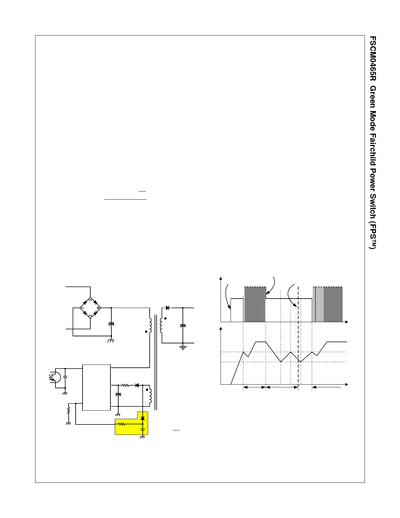
2.2 Constant Power Limit Circuit: Due to the circuit
delay of FPS, the pulse-by-pulse limit current increases
a little bit when the input voltage increases. This means
unwanted excessive power is delivered to the secondary
side. To compensate, the auxiliary power compensation
network in Figure 19 can be used. RLIM can adjust pulse-
by-pulse current by absorbing internal current source
(IFB: typical value is 0.9mA), depending on the ratio
between resistors. With the suggested compensation
circuit, additional current from IFB is absorbed more
proportionally to the input voltage (VDC) and achieves
constant power in wide input range. Choose RLIM for
proper current to the application, then check the pulse-
by-pulse current difference between minimum and
maximum input voltage. To eliminate the difference (to
gain constant power), Ry can be calculated by:
Ry
≅
Ilim_spec
× Vdc
×
Na
Np
Ifb × ΔIlim_comp
(3)
where, Ilim_spec is the limit current stated on the
specification; Na and Np are the number of turns for VCC
and primary side, respectively; Ifb is the internal current
source at feedback pin with a typical value of 0.9mA; and
ΔIlim_comp is the current difference which must be
eliminated. In case of capacitor in the circuit 1µF, 100V is
good choice for all applications.
2.3 Leading Edge Blanking (LEB): At the instant the
internal SenseFET is turned on, a high-current spike
through the SenseFET usually occurs, caused by
primary-side capacitance and secondary-side rectifier
reverse recovery. Excessive voltage across the Rsense
resistor can lead to incorrect feedback operation in the
current mode PWM control. To counter this effect, the
FSCM0465R employs a leading edge blanking (LEB)
circuit. This circuit inhibits the PWM comparator for a
short time after the SenseFET is turned on.
3. Protection Circuit: The FSCM0465R has several
self-protective functions, such as overload protection
(OLP), over-voltage protection (OVP) and thermal
shutdown (TSD). Because these protection circuits are
fully integrated into the IC without external components,
the reliability is improved without increasing cost. Once
the fault condition occurs, switching is terminated and
the SenseFET remains off. This causes VCC to fall.
When VCC reaches the UVLO stop voltage of 8V, the
current consumed by the FSCM0465R decreases to the
startup current (typically 20µA) and the current supplied
from the DC link charges the external capacitor (Ca)
connected to the VCC pin. When VCC reaches the start
voltage of 12V, the FSCM0465R resumes normal
operation. In this manner, the auto-restart can alternately
enable and disable the switching of the power SenseFET
until the fault condition is eliminated (see Figure 20).
Vds Power
On
Fault
occurs
Fault
removed
VDC
Np
L
Vfb Drain
Na
Vcc
RLIM
I_lim GND
RY
FSCM0465R Rev. 00
compensation
network
CY
-
+
Vy
=
VDC
×
Na
Np
Figure 19. Constant power limit circuit
Vcc
12V
8V
t
Normal
FSCM0465R Rev. 00 Operation
Fault
Situation
Normal
Operation
Figure 20. Auto Restart Operation
3.1 Overload Protection (OLP): Overload is defined as
the load current exceeding a preset level due to an
unexpected event. In this situation, the protection circuit
should be activated to protect the SMPS. However, even
when the SMPS is in the normal operation, the overload
protection circuit can be activated during the load
© 2006 Fairchild Semiconductor Corporation
FSCM0465R Rev. 1.0.1
11
www.fairchildsemi.com
Share Link: 