ILD32 データシートの表示(PDF) - Infineon Technologies
部品番号
コンポーネント説明
メーカー
ILD32 Datasheet PDF : 2 Pages
| |||
DUAL/QUADCHANNEL ILD32/ILQ32
Photodarlington Optocoupler
FEATURES
• Very High Current Transfer Ratio, 500% Min.
• Isolation Test Voltage, 5300 VRMS
• High Isolation Resistance, 1011 Ω Typical
• Low Coupling Capacitance
• Standard Plastic DIP Package
• Underwriters Lab File #E52744
•
V
DE
VDE 0884 Available with Option 1
Maximum Ratings (Each Channel)
Emitter
Peak Reverse Voltage ...................................... 3.0 V
Continuous Forward Current .......................... 60 mA
Power Dissipation at 25°C........................... 100 mW
Derate Linearly from 25°C ..................... 1.33 mW/°C
Detector
Collector-Emitter Breakdown Voltage ............... 30 V
Collector (Load) Current............................... 125 mA
Power Dissipation at 25°C Ambient ............ 150 mW
Derate Linearly from 25°C ....................... 2.0 mW/°C
Package
Isolation Test Voltage (between emitter
and detector refer to standard climate
23°C/50%RH, DIN 50014)
t=1.0 sec.............................................. 5300 VRMS
Creepage .................................................. ≥7.0 mm
Clearance .................................................. ≥7.0 mm
Comparative Tracking Index per
DIN IEC 112/VDE303, part 1 ........................ ≥175
Isolation Resistance
VIO=500V, TA=25°C ........................... RIO=1012 Ω
VIO=500V, TA=100°C ......................... RIO=1011 Ω
Total Dissipation at 25°C Ambient
ILD32 ...................................................... 400 mW
ILQ32 ...................................................... 500 mW
Derate Linearly from 25°C
ILD32 ................................................ 5.33 mW/°C
ILQ32 ................................................ 6.67 mW/°C
Storage Temperature .................... –55°C to +150°C
Operating Temperature ................ –55°C to +100°C
Lead Soldering Time at 260°C ..................... 10 sec.
DESCRIPTION
The ILD32/ILQ32 are optically coupled isolators
with a Gallium Arsenide infrared LED and a silicon
photodarlington sensor. Switching can be achieved
while maintaining a high degree of isolation
between driving and load circuits. These optocou-
plers can be used to replace reed and mercury
relays with advantages of long life, high speed
switching and elimination of magnetic fields.
The ILD32 has two isolated channels in a DIP pack-
age, and the ILQ32 has four channels. These
devices can be used to replace 4N32s or 4N33s in
applications calling for several single channel
optocouplers on a board.
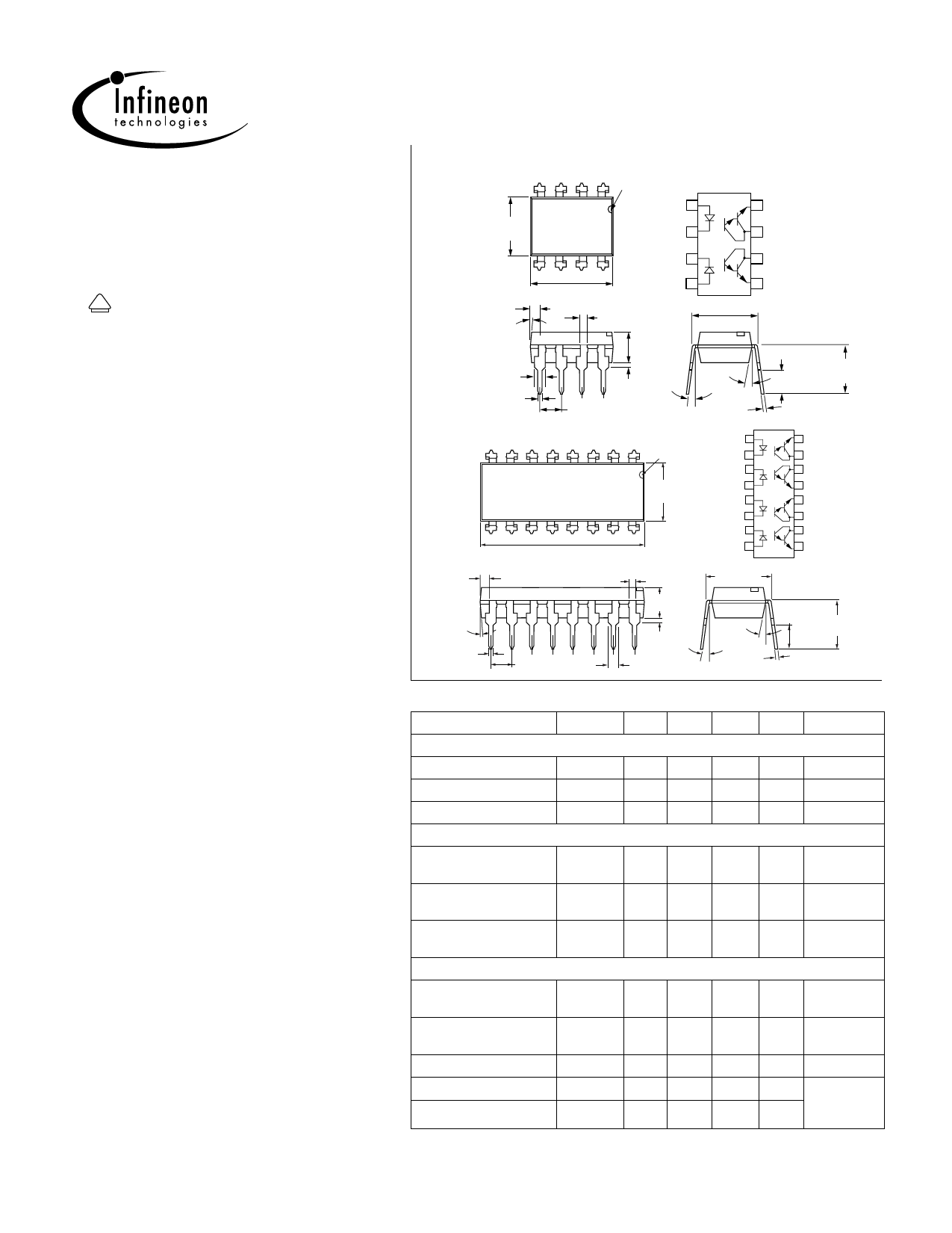
Dimensions in inches (mm)
Dual Channel
pin one ID
4 321
.255 (6.48)
.268 (6.81)
5 678
Anode 1
Cathode 2
Cathode 3
8 Emitter
7 Collector
6 Collector
.030 (0.76)
.045 (1.14)
4° typ.
.050 (1.27)
.018 (.46)
.022 (.56)
.379 (9.63)
.390 (9.91)
Anode 4
5 Emitter
.031 (0.79)
.300 (7.62)
typ.
.130 (3.30)
.150 (3.81)
.020 (.51 )
.035 (.89 )
.100 (2.54) typ.
10 °
3°–9°
.008 (.20)
.012 (.30)
.230(5.84)
.110 (2.79) .250(6.35)
.130 (3.30)
Quad Channel
Anode 1
16 Emitter
pin one ID Cathode 2
15 Collector
876543 21
Cathode 3
14 Collector
.255 (6.48)
.265 (6.81)
9 10 11 12 13 14 15 16
Anode 4
Anode 5
Cathode 6
13 Emitter
12 Emitter
11 Collector
.779 (19.77 )
.790 (20.07)
Cathode 7
Anode 8
10 Collector
9 Emitter
4°
.018 (.46)
.022 (.56)
.030 (.76)
.045 (1.14)
.031(.79)
.130 (3.30)
.150 (3.81)
.100 (2.54)typ.
.020(.51)
.035 (.89)
.050 (1.27)
.300 (7.62)
typ.
10°
typ.
3°–9°
.008 (.20)
.012 (.30)
.110 (2.79)
.130 (3.30) .230 (5.84)
.250 (6.35)
Table 1. Electrical Characteristics, TA=25°C
Parameter
Symbol Min. Typ. Max. Unit Condition
Emitter
Forward Voltage
VF
— 1.25 1.5 V
IF=10 mA
Reverse Current
IR
— 0.1 100 µA VR=3.0 V
Capacitance
CO
— 25 —
pF VR=0 V
Detector
Breakdown Voltage BVCEO 30 —
—
V
Collector-Emitter
Breakdown Voltage BVECO 5.0 10 —
V
Emitter-Collector
IC=100 µA
IF=0
IE=100 µA
Collector-Emitter
Leakage Current
Package
ICEO
— 1.0 100 nA VCE=10V
IF=0
Current Transfer Ratio CTR
500 —
—
%
IF=10 mA
VCE=10V
Collector Emitter
Saturation Voltage
VCEsat
—
—
1.0 V
IC=2.0 mA
IF=8.0 mA
Isolation Capacitance CISOL
— 0.5 —
pF —
Turn-On Time
Turn-Off Time
ton
— 15 —
µs VCC=10 V
toff
— 30 —
µs
IF=5.0 mA
RL=100 Ω
2001 Infineon Technologies Corp. • Optoelectronics Division • San Jose, CA
www.infineon.com/opto • 1-888-Infineon (1-888-463-4636)
2–179
February 24, 2000-21
Share Link: 