ISL36111DRZ-T7 データシートの表示(PDF) - Renesas Electronics
部品番号
コンポーネント説明
メーカー
ISL36111DRZ-T7 Datasheet PDF : 9 Pages
| |||
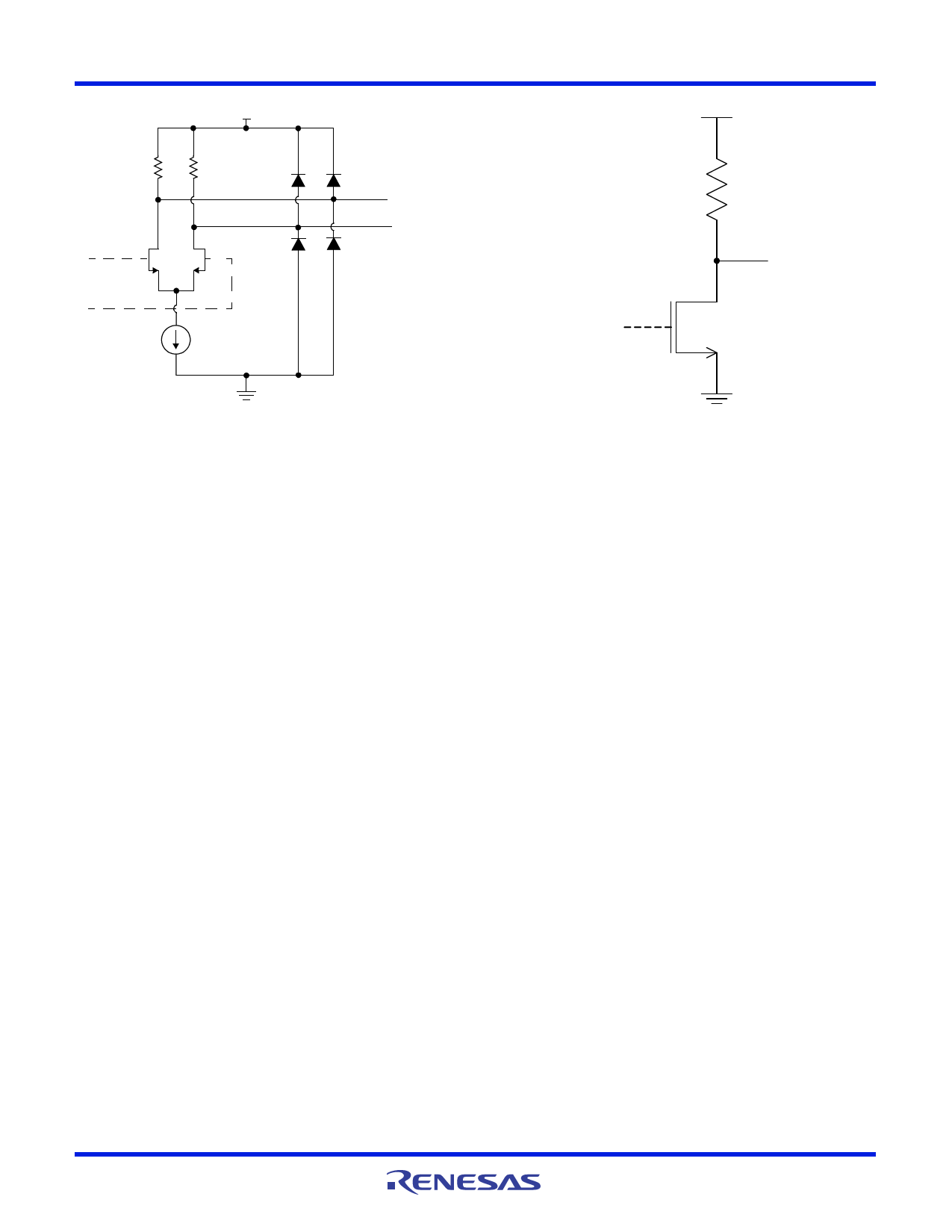
ISL36111
50Ω
VDD
50Ω
OUT [P]
OUT [N]
Internal LOS
Indicator
VDD
11k
LOSB
FIGURE 6. CML OUTPUT EQUIVALENT CIRCUIT FOR THE
ISL36111
Line Silence/Quiescent Mode
Line silence is commonly broken by the limiting amplification in
other equalizers. This disruption can be detrimental in many
systems that rely on line silence as part of the protocol. The
ISL36111 contains special lane management capabilities to
detect and preserve periods of line silence while still providing
the fidelity-enhancing benefits of limiting amplification during
active data transmission. Line silence is detected by measuring
the amplitude of the input signal and comparing that to a
threshold set by the voltage at the DT pin. When the amplitude
falls below the threshold, the output driver stage is muted.
LOS Bar Indicator
Pin 4 (LOSB) is used to output the state of the muting circuitry to
serve as a loss of signal indicator for the device. This signal is
directly derived from the muting signal output by the detection
threshold / signal detector comparator. The LOSB signal goes
LOW when the signal detector output is below the externally
controlled detection threshold and HIGH when the detector
output goes above this threshold. This feature is meant to be
used in optical systems (e.g. SFP+) where there are no quiescent
or electrical-idle states. In these cases, the detection threshold is
used to determine the sensitivity of the LOSB indicator. Figure 7
shows the schematic of the LOSB equivalent output structure.
FIGURE 7. LOSB EQUIVALENT OUTPUT STRUCTURE
Detection Thereshold (DT) Pin
Functionality
The ISL36111 is capable of maintaining periods of line silence by
monitoring the channel for loss of signal (LOS) conditions and
subsequently muting the output driver when such a condition is
detected. A reference voltage applied to the detection threshold
(DT) pin is used to set the LOS threshold of the internal signal
detection circuitry. The DT voltage is set with an external pull-up
resistor, RDT. For typical applications, a 30k resistor is
recommended for channels with loss greater than 12dB at 5GHz,
and a 1.8k resistor is recommended for lower loss channels.
Other values of the resistor may also be applicable; therefore DT
settings should be verified on an application-specific basis.
FN6974 Rev 2.00
Jul 12, 2012
Page 6 of 9
Share Link: 