MSB709 データシートの表示(PDF) - Weitron Technology
部品番号
コンポーネント説明
メーカー
MSB709 Datasheet PDF : 6 Pages
| |||
MSB709
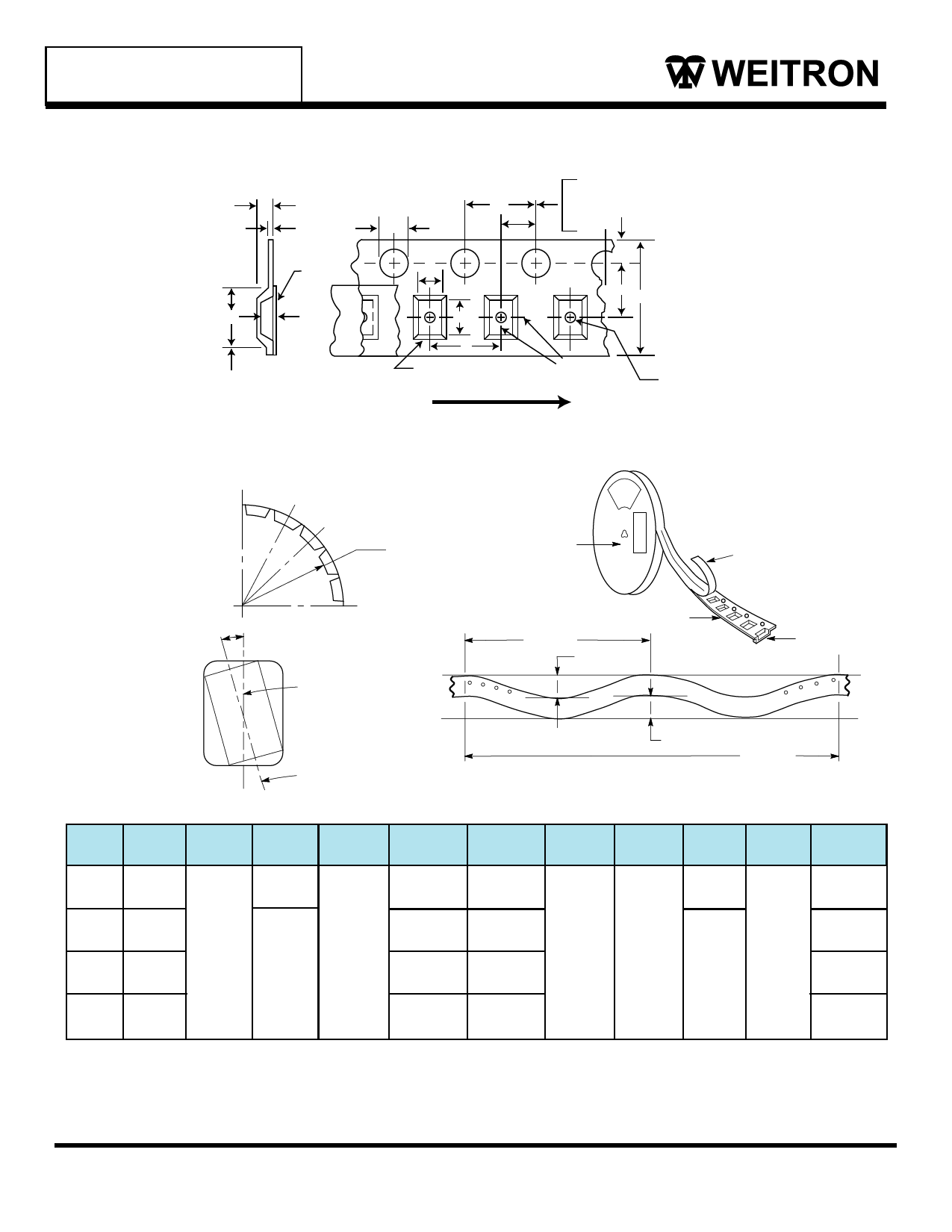
EMBOSSED TAPE AND REEL DATA FOR DISCRETES
CARRIER TAPE SPECIFICATIONS
K
t
Top Cover
Tape
B1
K0
# Note 1
P0
D
A0
B0
P
Embossment
10 Pitches Cumulative Tolerance on Tape
±0.2 mm
P2
E
FW
Center Lines
of Cavity
D1
For Components
2.0 mm x 1.2 mm and Larger
FOR MACHINE REFERENCE ONLY0
INCLUDING DRAFT AND RADII
CONCENTRIC AROUND B0
User Direction of Feed
10°
DIMENSIONS
Size
B1 Max
#(Note 2)
D
R Min
Barcode Label
Bending Radius
Tape and Components
Shall Pass Around Radius “R”
Without Damage
Maximum Component Rotation
Embossed Carrier
100 mm
1 mm Max
Typical Component
Cavity Center Line
Top Cover Tape Thickness
0.10 mm Max.
Embossment
Tape
Typical Component
Center Line
1 mm Max
250 mm
Camber (Top View)
Allowable Camber To Be 1 mm/100 mm Nonaccumulative Over 250 mm
D1
E
F
K
P0
P2 R Min T Max W Max
8mm 4.55 mm 1.5+0.1 mm 1.0 Min 1.75±0.1 mm 3.5±0.05 mm 2.4 mm Max 4.0±0.1 mm 2.0±0.1 mm 25 mm
-0.0
12mm 8.2 mm
1.5 mm Min
5.5±0.05 mm 6.4 mm Max
30 mm
0.6 mm
8.3 mm
12±0.3 mm
16mm 12.1 mm
7.5±0.10 mm 7.9 mm Max
16.3 mm
24mm 20.1 mm
11.5±0.1 mm 11.9 mm Max
Metric dimensions govern - English are in parentheses for reference only.
NOTE 1: A 0, B 0 , and K0 are determined by component size. The clearance between the components and the cavity must be within
.05 mm min. to.50 mm max.,
NOTE 2: the component cannot rotate more than 10 o within the determined cavity.
NOTE 3: If B1exceeds 4.2 mm for 8 mm embossed tape, the tape may not feed through all tape feeders.
24.3 mm
WEITRON
5/6
http://www.weitron.com.tw
18-Sep-06
Share Link: 