MM1142XF データシートの表示(PDF) - Mitsumi
部品番号
コンポーネント説明
メーカー
MM1142XF Datasheet PDF : 5 Pages
| |||
MITSUMI
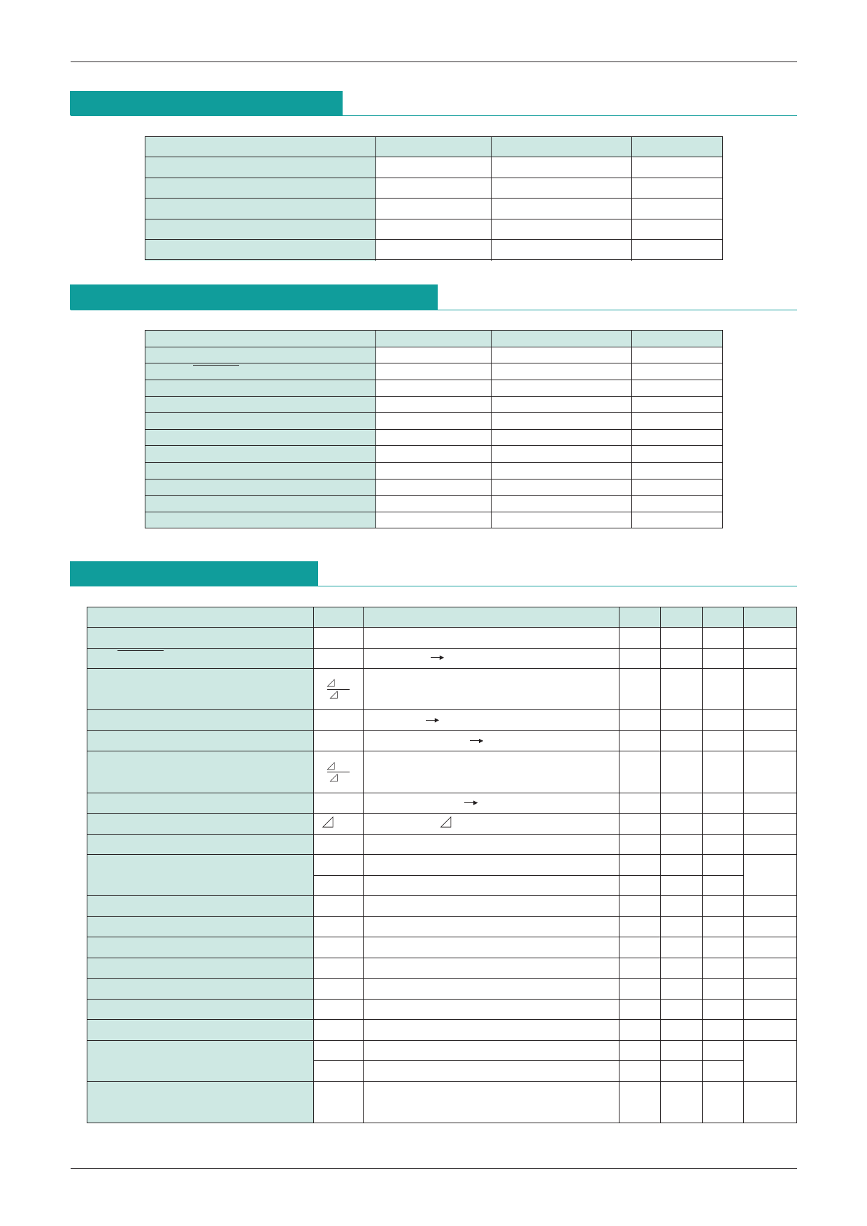
System Reset (with built-in watchdog timer) MM1142
Absolute Maximum Ratings (Ta=25°C)
Item
Power supply voltage
Voltage applied to input pin
Voltage applied to output pin
Allowable loss
Storage temperature
Symbol
VCC max.
VIN
VOUT
Pd
TSTG
Recommended Operating Conditions
Item
Power supply voltage
RESET sync current
BC sync current
Clock input high level voltage
Clock input low level voltage
Clock monitoring time setting
Clock rise and fall times
Power supply voltage rise times
Power supply voltage fall times
TC pin capacitance
Operating temperature
Symbol
VCC
IOLR
IOLC
VCKH
VCKL
TWD
tRCK, tFCK
tRVCC
tFVCC
CT
TOP
Rating
-0.3~+7
-0.3~VCC+0.3 ( <= +7)
-0.3~VCC+0.3 ( <= +7)
300
-40~+125
Rating
+1.9~+6.5
0~500
0~5.0
1.0<
<0.2
1~10000
<100
100<
50<
0.0022~2.2
-20~+70
Units
V
V
V
mW
°C
Units
V
µA
mA
V
V
mS
µS
µS
µS
µF
°C
Electrical Characteristics (Except where noted otherwise, Ta=25°C, VCC=2.6V)
Item
Symbol
Measurement conditions
Min. Typ. Max. Units
Consumption current
ICC
No load
200 280 µA
RESET detection voltage
VSLR VCC : High Low, RCT : GND, VTC=OPEN
2.00 ±3% V
Detection voltage temperature VSR
coefficient R
T
±0.01 ±0.05 %/°C
Hysteresis voltage R
VHYSR VCC : Low High, RCT=GND, VTC=OPEN 25 50 100 mV
BC detection voltage
VSLB
VCC : High Low, RLB=10kΩ
2.20 ±3% V
Detection voltage temperature VSB
coefficient B
T
±0.01 ±0.05 %/°C
Hysteresis voltage B
VHYSB
VCC : Low High, RLB=10kΩ
25 50 100 mV
Detection voltage difference
VSL
VSL=VSLB-VSLR
0.175 0.200 0.225 V
CK input threshold
VTH
0.4 0.6 1.2 V
IIH
CK input current
IIL
VCK=2.6V
VCK=0.0V
01
-15 -6 -2 µA
Output voltage RH
VOHR
IRESET=-1µA --------------------------------------------
2.0 2.2
V
Output voltage BH
VOHB
RLB=10kΩ
2.0 2.2
V
Output voltage RL
VOLR
I =500µA, V =1.8V --------------------------------------------
RESET
CC
0.3 0.5 V
Output voltage BL
VOLB
IBC=5mA, VCC=1.8V
0.3 0.5 V
Output sync current R
IOLR
V =0.5V, V =1.8V --------------------------------------------
RESET
CC
500 700
µA
Output sync current B
IOLB
VBC=0.5V, VCC=1.8V
57
mA
Output source current R
IOHR
VRESET=2.0V --------------------------------------------
24
µA
CT charge current
ICT1 VTC=0.5V during watchdog timer operation -0.300 -0.150 -0.075
ICT2 VTC=0.5V during power ON reset operation -0.300 -0.150 -0.075 µA
Minimum operating power supply voltage
-------------------------------------------------------------------------------
to ensure RESET
VCCL
VRESET=0.4V, IRESET=0.05mA ---------------------------------------------
---------------------------------------------
0.8 1.0 V
Share Link: 