PDM31256SA10TA データシートの表示(PDF) - Paradigm Technology
部品番号
コンポーネント説明
メーカー
PDM31256SA10TA Datasheet PDF : 7 Pages
| |||
PDM31256
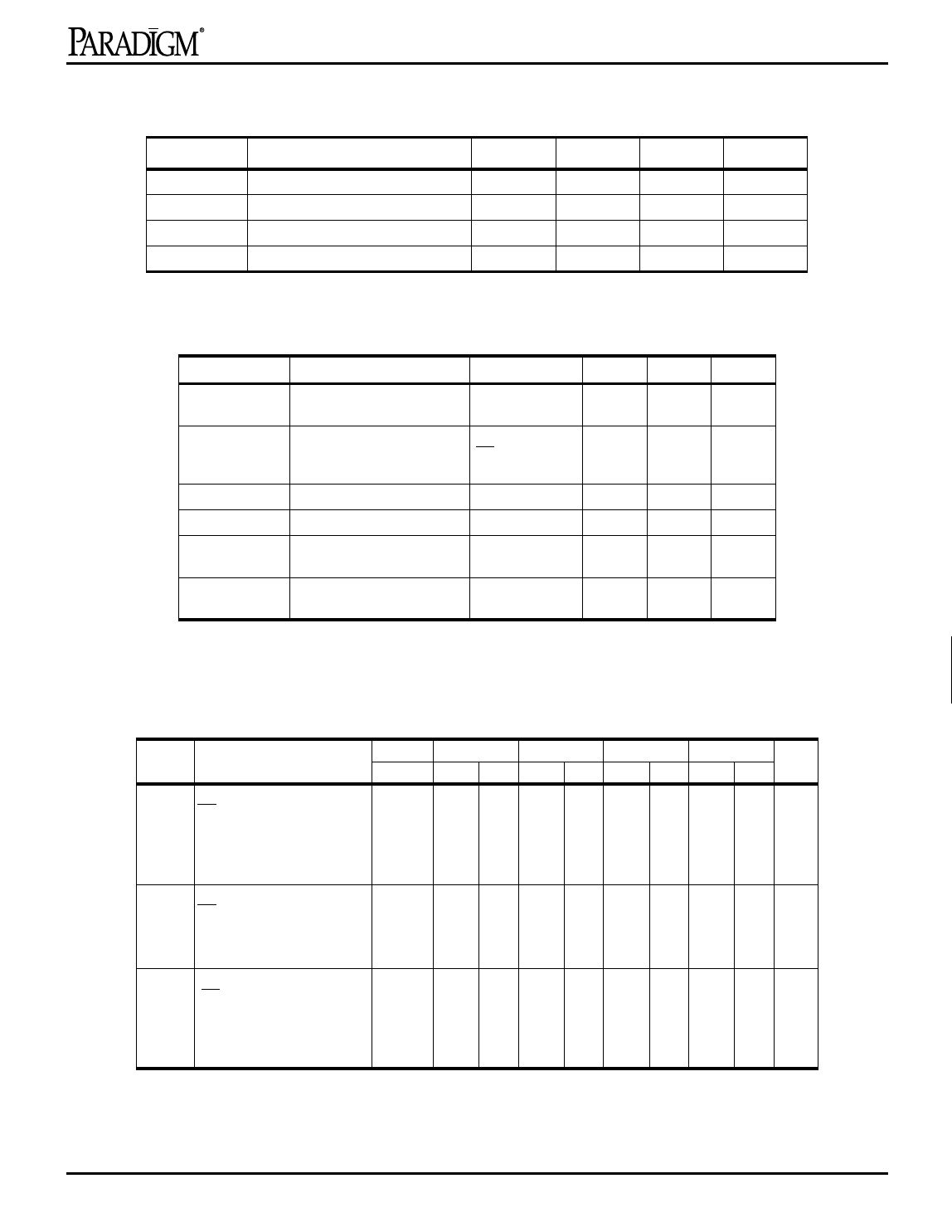
Recommended DC Operating Conditions
Symbol
VCC
Parameter
Supply Voltage
Min.
Typ.
Max.
Unit
1
3.0
3.3
3.6
V
VSS
Supply Voltage
0
0
0
V
Commercial
Industrial
Ambient Temperature
Ambient Temperature
0
25
70
°C
–40
25
85
°C
2
DC Electrical Characteristics (VCC = 3.3V ± 0.3V)
Symbol
Parameter
Test Conditions Min.
Max.
Unit
ILI
Input Leakage Current
VCC = MAX., VIN
–5
5
µA
= Vss to VCC
ILO
Output Leakage Current
VCC= MAX.,
–5
5
µA
CE = VIH, VOUT =
Vss to VCC
VIL
Input Low Voltage
–0.3(1)
0.8
V
VIH
Input High Voltage
2.2 Vcc+0.3
V
VOL
Output Low Voltage
IOL= 8 mA
—
0.4
V
VCC = Min.
VOH
Output High Voltage
IOH = –4 mA,
2.4
—
V
VCC = Min.
NOTE:1.VIL(min) = –3.0V for pulse width less than 20 ns.
Power Supply Characteristics
-10
-12
-15
-17
-20
Symbol Parameter
ICC Operating Current
CE = VIL
f = fMAX = 1/tRC
VCC = Max.
IOUT = 0 mA
ISB Standby Current
CE = VIH
f = fMAX = 1/tRC
VCC = Max.
ISB1 Full Standby Current
CE ≥ VCC – 0.2V
f=0
VCC = Max.,
VIN ≥ VCC – 0.2V or ≤ 0.2V
Com’l. Com’l Ind. Com’l Ind. Com’l Ind. Com’l Ind. Unit
140 130 130 120 120 120 120 110 110 mA
45
40 35 35 35 35 35 30 30 mA
10
10 15 10 15 10 15 10 15 mA
NOTES: All values are maximum guaranteed values.
3
4
5
6
7
8
9
10
11
12
Rev. 3.3 - 4/29/98
3
Share Link: 