MAX1802EVKIT データシートの表示(PDF) - Maxim Integrated
部品番号
コンポーネント説明
メーカー
MAX1802EVKIT Datasheet PDF : 7 Pages
| |||
MAX1802 Evaluation Kit for
Digital Still Cameras
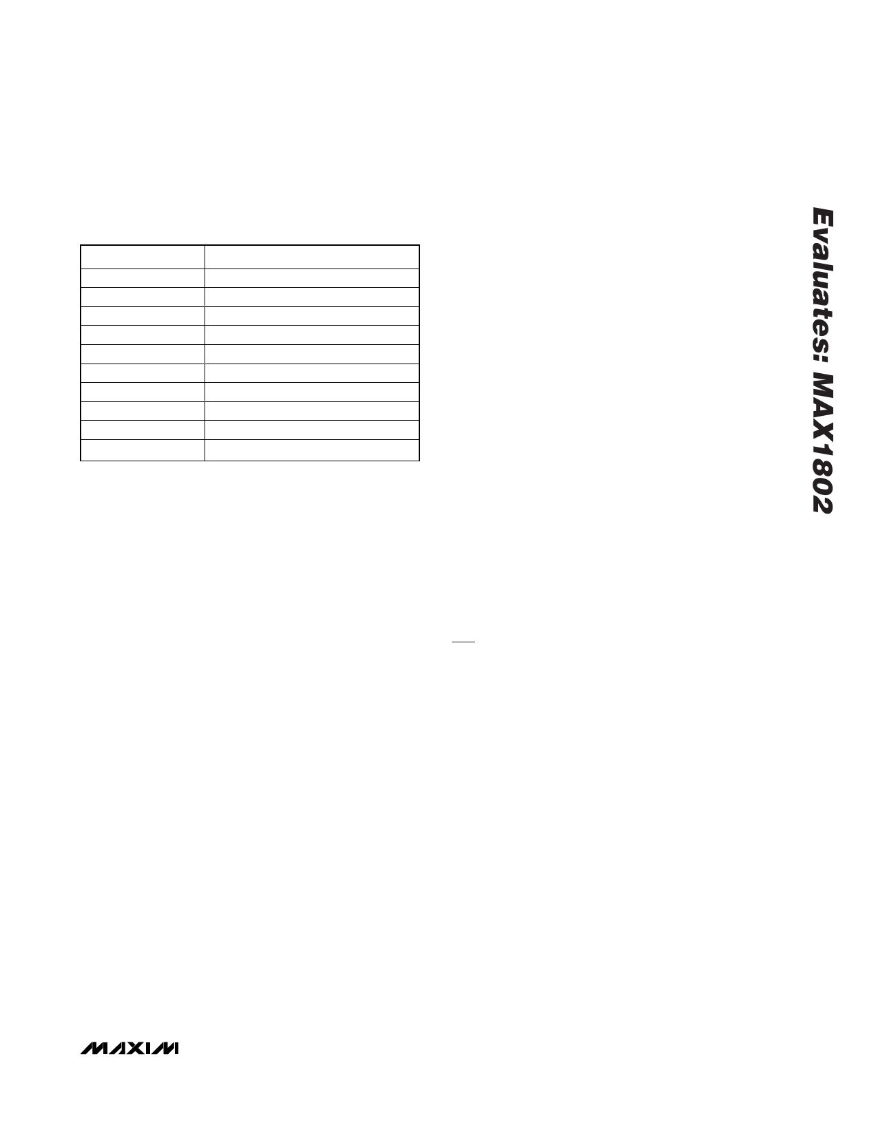
Table 1. Output Voltage and Current
Capability
LABEL
MAIN
CORE
OUT1A
OUT1B
OUT1C
OUT2A
OUT2B
OUT2C
OUT3
OUT4
VOLTAGE/CURRENT
+3.3V at 1A
+1.8V at 400mA
+13.5V at 10mA
+5V at 50mA
-9V at 10mA
+13.5V at 10mA
+5V at 50mA
-19.0V at 10mA
+7V at 100mA
+12V at 100mA
OUT1_ (Flyback Outputs)
The voltages at OUT1_ are typical of CCD bias voltages.
The output voltages are +13.5V/10mA, +5V/50mA, and
-9V/10mA. These voltages are generated through a cus-
tom flyback transformer. OUT1B (+5V) is used to regu-
late the flyback circuit. The other output voltages
(+13.5V and -9V) are controlled by the turns-ratio of the
flyback transformer. If the +13.5V and -9V outputs are
not loaded at the fixed 10mA load, then the output volt-
age will change from the nominal loaded output voltage.
Loads are included on the MAX1802 EV kit by shorting
jumpers JU7 through JU12. If external loads are used,
remove these jumpers to disable the built-in loads.
To enable OUT1_, place jumper JU6 to the ON position.
To disable OUT1_, place jumper JU6 to the OFF posi-
tion. To enable and disable the output voltages using an
external signal, see the Logic Control of the Output
Voltages section.
If a different set of output voltages is required, see the
Setting the Flyback Circuit Voltages section.
OUT2_ (Flyback Outputs)
The voltages at OUT2_ are typical of LCD bias volt-
ages. The output voltages are +13.5V/10mA,
+5V/50mA, and -19V/10mA. These voltages are gener-
ated through a custom flyback transformer. OUT2B
(+5V) is used to regulate the flyback circuit. The other
output voltages (+13.5V and -19V) are controlled by the
turns-ratio of the flyback transformer. If the +13.5V and
-19V outputs are not loaded at the fixed 10mA load,
then the output voltage will change from the nominal
loaded output voltage. Loads are included on the
MAX1802 EV kit by shorting jumpers JU7 through
JU12. If external loads are used, disable the built-in
loads by removing these jumpers.
To enable OUT2_, place jumper JU2 to the ON posi-
tion. To disable OUT2_, place jumper JU2 to the OFF
position. To enable and disable the output voltages
using an external signal, see the Logic Control of the
Output Voltages section.
If a different set of output voltages is required, see the
Setting the Flyback Circuit Voltages section.
OUT3
The voltage at OUT3 is typical of that required by a
CCFL backlight inverter. To enable OUT3, place jumper
JU3 to the ON position. Place the external load
between OUT3 and GND. To change the output voltage
of OUT3, see the Setting the Step-Up Output Voltage
section. OUT3 is configured for a 7V output. For input
voltages greater than 7V, the output will approximately
track the input.
OUT3 can be configured to drive a white LED backlight
instead of a CCFL backlight.
OUT4
The voltage at OUT4 is a general-purpose +12V output
that can supply up to 100mA. To enable OUT4, place
jumper JU1 to the ON position. Place the external load
between OUT4 and GND. To change the output voltage
of OUT4, see Setting the Step-Up Output Voltage sec-
tion.
Customizing the MAX1802 EV Kit
Setting the Main Output Voltage
MAIN is set by a voltage-divider, which drops the out-
put voltage to the +1.25V feedback threshold voltage.
To change the 3.3V setting of MAIN, change the resis-
tor-divider ratio by changing R23. Use:
R23 = 80kΩ/V x (VOUT - 1.248V)
The MAIN output voltage may be set to any voltage
between +2.7V and +5.5V. For additional information,
refer to the MAX1802 IC data sheet.
Setting the Core Output Voltage
CORE is set by a voltage-divider, which drops the out-
put voltage to the +1.25V feedback threshold voltage.
To change the +1.8V setting of CORE, change the
resistor-divider ratio by changing R21. Use:
R21 = 80kΩ/V x (VCORE - 1.248V)
CORE may be set to any voltage between +1.25V and
+5.5V but must remain less than the voltage at MAIN.
The MAX1802 EV kit is configured so that MAIN powers
the CORE input.
_______________________________________________________________________________________ 3
Share Link: 