LC72344W データシートの表示(PDF) - SANYO -> Panasonic
部品番号
コンポーネント説明
メーカー
LC72344W Datasheet PDF : 13 Pages
| |||
LC72344W, 72345W
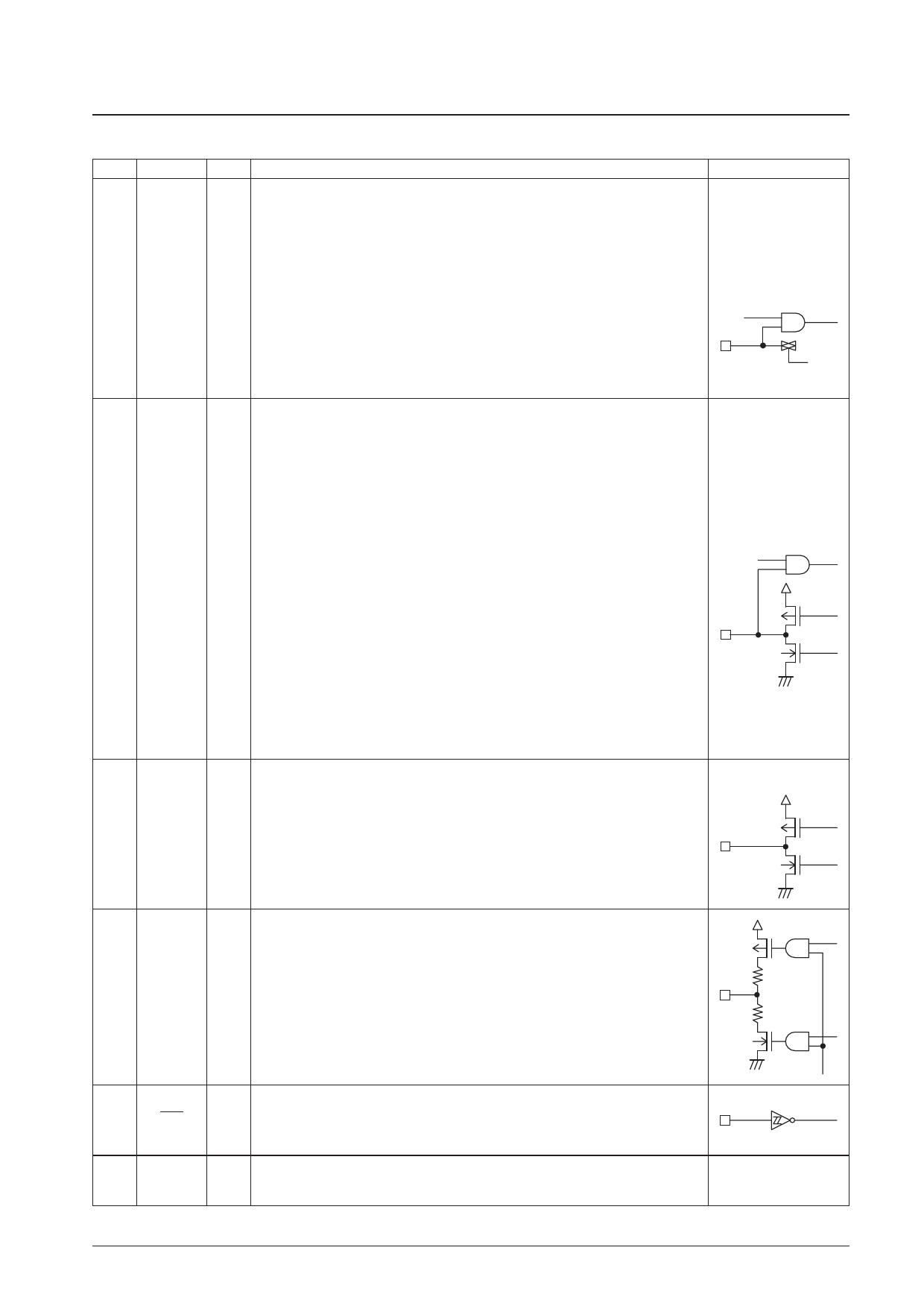
Continued from preceding page.
Pin No.
Pin
23 PF0/ADI0
22 PF1/ADI1
I/O
Function
I/O circuit
General-purpose input and A/D converter input shared function ports.
The IOS instruction (Pwn = FH) is used to switch between the general-purpose input and A/D
converter port functions. The general-purpose input and A/D converter port functions can be CMOS input/analog input
switched in a bit units, with 0 specifying general-purpose input, and 1 specifying the A/D
converter input function. To select the A/D converter function, set up the A/D converter pin
with an IOS instruction with Pwn set to 1. The A/D converter is started with the UCC
I
instruction (b3 = 1, b2 = 1). The ADCE flag is set when the conversion completes. The INR
instruction is used to read in the data.
*: If an input instruction is executed for one of these pins which is set up for analog input, the
read in data will be at the low level since CMOS input is disabled. In backup mode these pins
go to the input disabled high-impedance state. These ports are set to their general-purpose
input port function after a reset. The A/D converter is a 5-bit successive approximation type
converter, and features a conversion time of 1.28 ms. Note that the full-scale A/D converter
voltage (1FH) is (63/96) times VDC3.
LCD driver segment output and general-purpose I/O shared function ports.
The IOS instruction* is used for switching both between the segment output and general-
purpose I/O functions and between input and output for the general-purpose I/O port function.
• When used as segment output ports
CMOS push-pull output
31
PG3/S19
The general-purpose I/O port function is selected with the IOS instruction (Pwn = 8).
32
PG2/S18
b0 = S16 to 19/PG0 to 3 (0: Segment output, 1: PG0 to 3)
33
PG1/S17
The general-purpose I/O port function is selected with the IOS instruction (Pwn = 9).
34
PG0/S16
b0 = S12 to 15/PH0 to 3 (0: Segment output, 1: PH0 to 3)
• When used as general-purpose I/O ports
O
35
PH3/S15
36
PH2/S14
37
PH1/S13
38
PH0/S12
The IOS instruction (Pwn = 6,7) is used to select input or output. Note that the mode can
be set in a bit units.
b0 = PG0
b1 = PG1
b2 = PG2
( ) 0: Input
1: Output
b0 = PH0
( ) b1 = PH1 0: Input
b2 = PH2 1: Output
(*)
b3 = PG3
b3 = PH3
In backup mode, these pins go to the input disabled high-impedance state if set up as
general-purpose outputs, and are fixed at the low level if set up as segment outputs. These
ports are set up as segment outputs after a reset.
Although the general-purpose port/LCD port setting is a mask option, the IOS instruction
must be used as described above to set up the port function.
39 to 49 S11 to S1
LCD driver segment output pins.
A 1/4-duty 1/2-bias drive technique is used.
O The frame frequency is 75 Hz.
In backup mode, these outputs are fixed at the low level.
After a reset, these outputs are fixed at the low level.
CMOS push-pull output
50
COM4
51
COM3
52
COM2
53
COM1
LCD driver common output pins.
A 1/4-duty 1/2-bias drive technique is used.
O The frame frequency is 75 Hz.
In backup mode, these outputs are fixed at the low level.
After a reset, these outputs are fixed at the low level.
54
RES
21
BATT
System reset input.
I In CPU operating mode or halt mode, applications must apply a low level for at least one full
machine cycle to reset the system and restart execution with the PC set to location 0. This
pin is connected in parallel with the internal power on reset circuit.
Battery presence/absence discrimination.
I The internal clock oscillator starts when a high level is input to this pin.
The IN instruction can be used to determine whether or not a battery is present.
Continued on next page.
No. 6171-8/13
Share Link: 