BA7780 データシートの表示(PDF) - ROHM Semiconductor
部品番号
コンポーネント説明
メーカー
BA7780 Datasheet PDF : 10 Pages
| |||
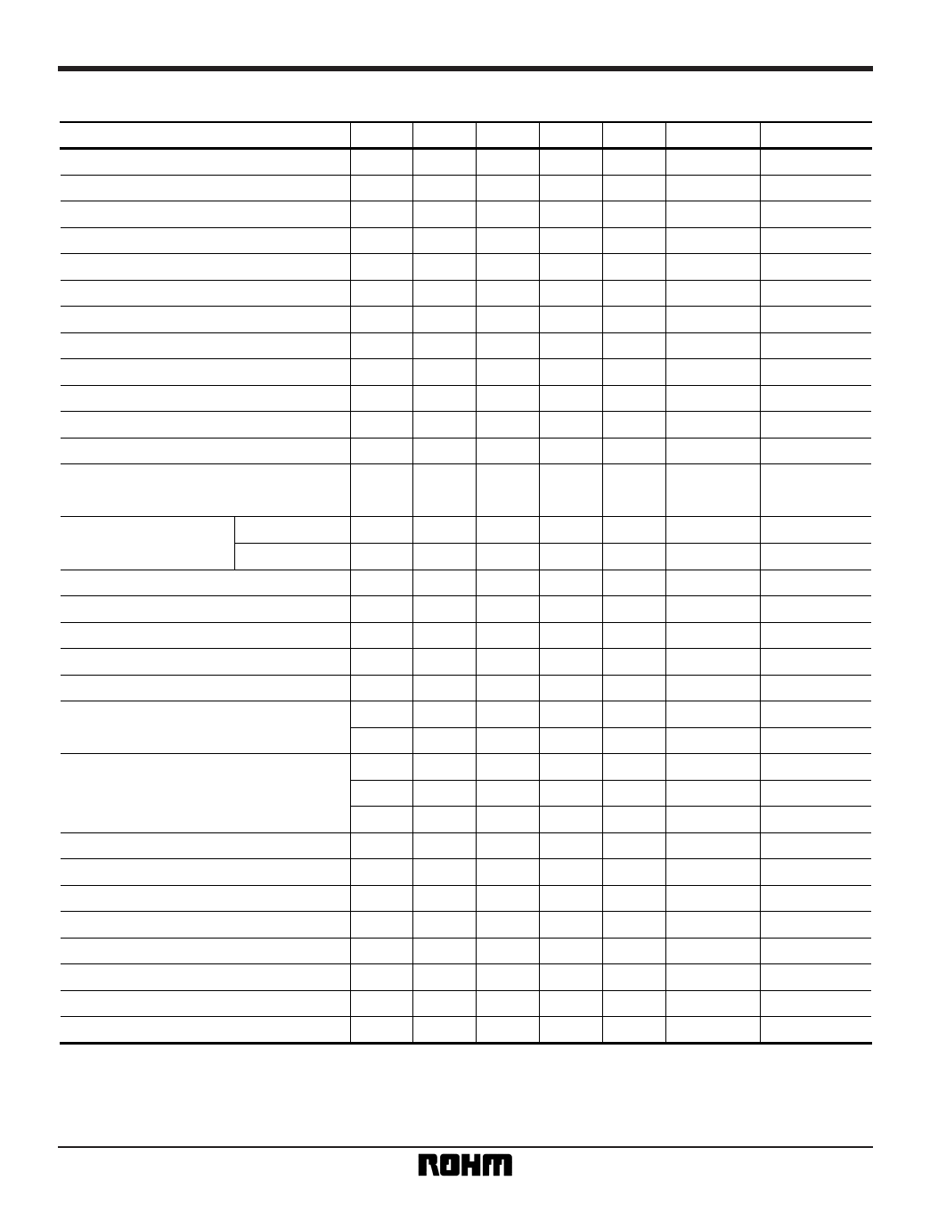
Video ICs
BA7780KV
•Measurement circuit switching table (blank cells: no spesification)
Parameter
Current dissipation
Voltage gain 1
Voltage gain 2
Voltage gain 3
Voltage gain 4
Distortion 1
Distortion 2
Distortion 3
Maximum output
Output noise voltage 1 (EXT)
Output noise voltage 2 (WIDE)
Output noise voltage 3 (ZOOM)
SW1
1
—
—
—
—
2
2
1
1
2
2
3
SW2
1
—
—
—
—
—
—
—
—
—
—
—
SW3
1
—
—
—
—
—
—
—
—
—
—
—
MODE6 MODE43 GAIN CTL
H, L H, L
M
L
L
M
H
—
H
—
—
M
—
—
L
H
L
M
L
L
—
H
L
M
H, L
L
L
L
L
—
H
L
H
H
L
H
Signal input pin
—
Ext
Int
Int
Int
Int
Ext
Sub
Int, Ext, Sub
—
—
—
Input switch crosstalk (INT to EXT)
2
—
—
L
L
L
Int
INT
2
—
—
H
L
M
Int
Interchannel crosstalk
EXT
2
—
—
L
L
—
Ext
GC out L / R gain differential
1
—
—
H
L
H, M, L
Int
Inverter OUT L / R gain differential
1
—
—
H
L
H, M, L
Int
Internal microphone power supply voltage
—
—
—
—
—
—
—
External power supply output voltage
—
—
—
—
—
—
—
External power supply limit current
—
—
—
—
—
—
—
Input switching CTL holding voltage
2
—
—
H
Vth
—
2
—
—
Vth
L
—
Int, Ext
Int, Ext
2
—
—
H
L
Vth
Int
Gain switching CTL holding voltage
2
—
—
H
L
Vth
Int
2
—
—
H
L
Vth
Int
HPF, CTL holding voltage
2
2.1
2.1
H
L
—
Int, Vth of pin 19
MIX 1 gain
—
—
—
H
L
M
Int
MIX 2 gain
—
—
—
H
L
—
Sub
ZOOM - BALANCE Gain 1
2
—
—
H
L
M
Int
ZOOM - BALANCE Gain 2
1
—
—
H
L
M
Sub
ZOOM - BALANCE Variable position
2
—
—
H
L
M
Int
ZOOM - BALANCE Variable inclination
2
—
—
H
L
M
Int
Sub VCA gain
—
—
—
H
L
—
Sub
∗ Gain CTL pin 26.
H, M, and L are VCC, 1/2VCC, and GND respectively.
Measure the voltage range that maintains the mode for Vth.
8
Share Link: 