BA5912BFP データシートの表示(PDF) - ROHM Semiconductor
部品番号
コンポーネント説明
メーカー
BA5912BFP Datasheet PDF : 6 Pages
| |||
3/5
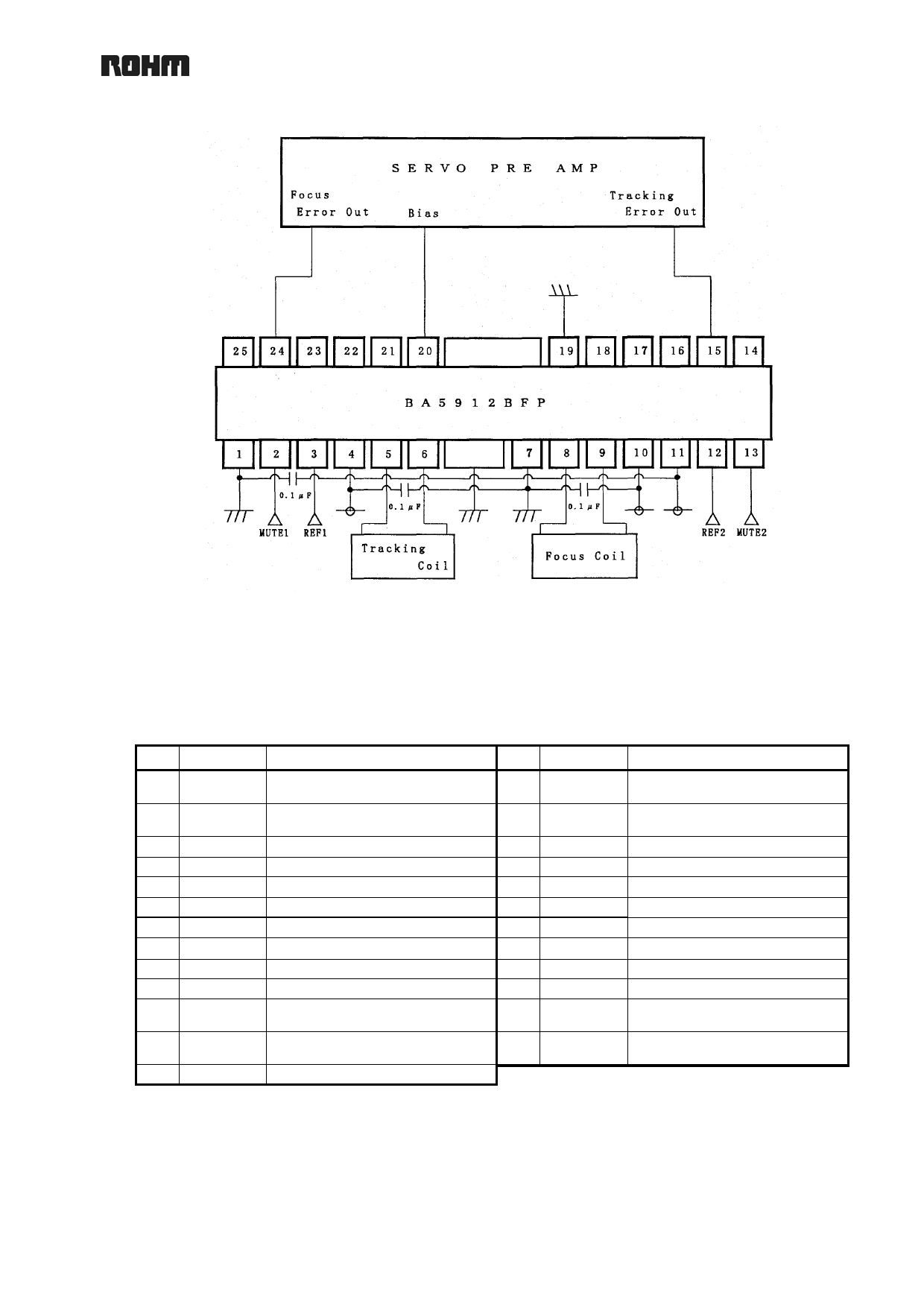
{ APPLICATION CIRCUIT DIAGRAM
When used at Pre Vcc > Pow Vcc + VF and in the standby mode, REF1 (PIN3) and REF2 (PIN12) must be
set to open, or 0.5V or less. When used with REF1 (PIN3) and REF2 (PIN12) shorted; or MUTE1 (PIN2)
and MUTE2 (PIN13) shorted, each microcomputer output must be able to supply a current of 300µA or so.
{ PIN NUMBERS, PIN NAMES
No. Pin Name
Description
1
GND Substrate GND
2
MUTE1 CH1 mute terminal
3
REF1 CH1Vref switching terminal
4 Pow Vcc1 Pow Vcc(CH1)
5
OUT1- CH1 negative output terminal
6
OUT1+ CH1 positive output terminal
7
GND Substrate GND
8
OUT2+ CH2 positive output terminal
9
OUT2- CH2 negative output terminal
10 Pow Vcc2 Pow Vcc(CH2)
11 Pre Vcc Pre Vcc
12
REF2 CH2Vref switching terminal
13 MUTE2 CH2 mute terminal
No. Pin Name
Description
14
IN2’
CH2 input terminal for gain
control
15
IN2
CH2 input terminal with gain
fixed
16 OP1-OUT Operational amplifier 1 output
17 OP1-IN- Operational amplifier 1- input
18 OP-IN+ Operational amplifier 1+ input
19
GND Substrate GND
20
BIAS Bias input terminal
21 OP2-IN+ Operational amplifier 2+ input
22 OP2-IN- Operational amplifier 2- input
23 OP2-OUT Operational amplifier 2 output
24
IN1
CH1 input terminal with gain
fixed
25
IN1’
CH1 input terminal for gain
control
* The positive or negative polarity on an output
terminal is determine by the input polarity.
REV. A
Share Link: 