ACPL-M60L データシートの表示(PDF) - Broadcom Corporation
部品番号
コンポーネント説明
メーカー
ACPL-M60L Datasheet PDF : 14 Pages
| |||
ACPL-M60L
Data Sheet
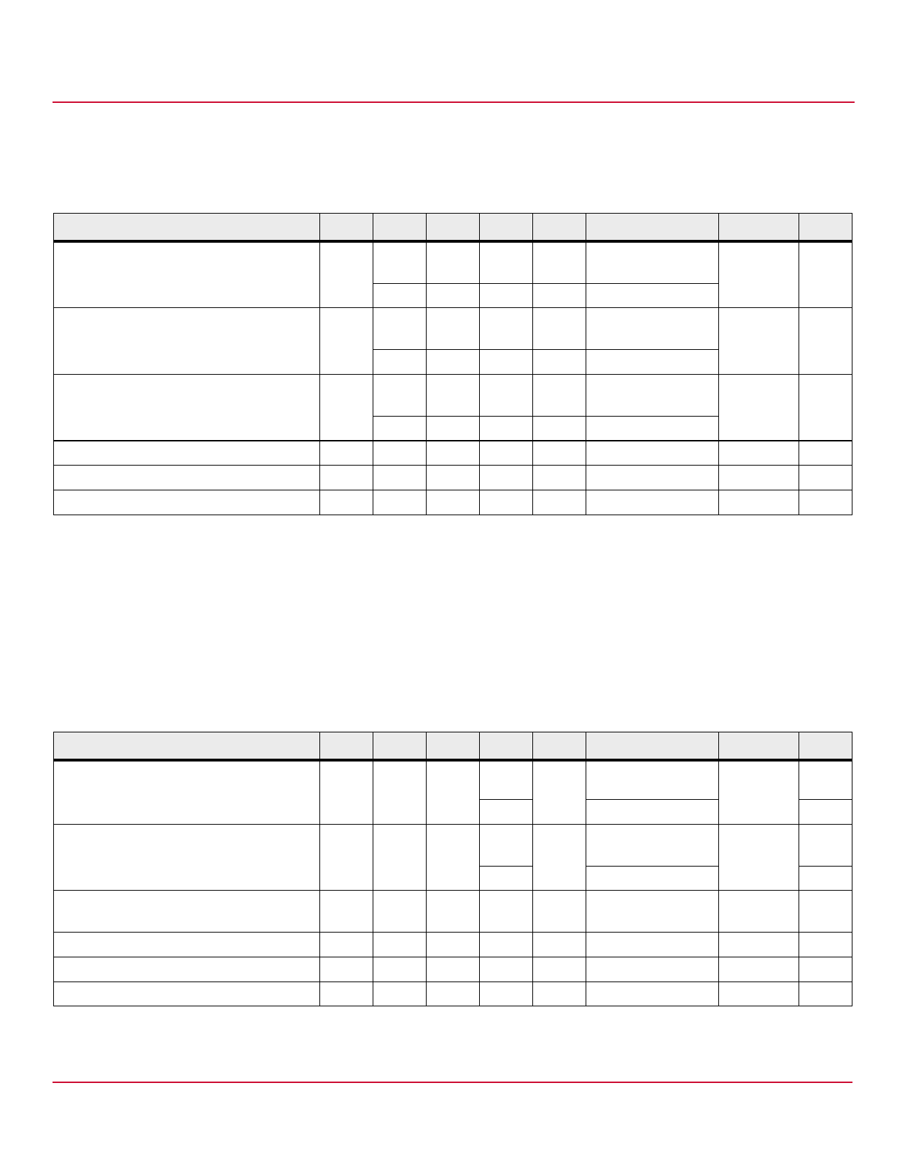
Switching Specifications
Over recommended temperature (TA = –40°C to +100°C), VCC = 3.3V, IF = 7.5 mA unless otherwise specified.
All Typical specifications at TA = 25°C, VCC = 3.3V.
Table 1 Switching Specifications
Parameter
Symbol Min. Typ. Max. Units Test Conditions
Fig.
Note
Propagation Delay Time to High Output Level tPLH
—
—
90
ns TA = –40°C to 85°C,
13, 14
a, b
RL = 350Ω, CL = 15 pF
—
—
95
ns RL = 350Ω, CL = 15 pF
Propagation Delay Time to Low Output Level tPHL
—
—
75
ns TA = –40°C to 85°C,
13, 14
b, c
RL = 350Ω, CL = 15 pF
—
—
90
ns RL = 350Ω, CL = 15 pF
Pulse Width Distortion
|tPHL – —
—
25
ns TA = –40°C to 85°C,
16
b
tPLH|
RL = 350Ω, CL = 15 pF
—
—
30
ns RL = 350Ω, CL = 15 pF
Propagation Delay Skew
tPSK
—
—
40
ns RL = 350Ω, CL = 15 pF
Output Rise Time (10-90%)
tr
—
45
—
ns RL = 350Ω, CL = 15 pF
Output Fall Time (90-10%)
tf
—
20
—
ns RL = 350Ω, CL = 15 pF
a. The tPLH propagation delay is measured from the 3.75 mA point on the falling edge of the input pulse to the 1.5 V point on the rising edge of the output pulse.
b. See test circuit for measurement details.
c. The tPHL propagation delay is measured from the 3.75 mA point on the rising edge of the input pulse to the 1.5 V point on the falling edge of the output pulse.
NOTE JEDEC registered data for the 6N137.
Switching Specifications
Over recommended temperature (TA = –40°C to 100°C), VCC = 5V, IF = 7.5 mA unless otherwise specified.
All Typical specifications at TA = 25°C, VCC = 5V.
Table 2 Switching Specifications
Parameter
Symbol Min. Typ. Max. Unit
Test Conditions
Propagation Delay Time to High Output Level tPLH
20
48
75
ns TA = 25°C, RL=350Ω,
CL=15 pF
100
RL=350Ω, CL=15 pF
Propagation Delay Time to Low Output Level tPHL 25
50
75
ns TA = 25°C, RL=350Ω,
CL=15 pF
100
RL= 350Ω, CL = 15 pF
Pulse Width Distortion
|tPHL – —
3.5
35
ns RL= 350Ω, CL = 15 pF
tPLH|
Propagation Delay Skew
tPSK
—
—
40
ns RL= 350Ω, CL = 15 pF
Output Rise Time (10%–90%)
trise
—
24
—
ns RL= 350Ω, CL = 15 pF
Output Fall Time (10%–90%)
tfall
—
10
—
ns RL= 350Ω, CL = 15 pF
Figure
13, 15
13, 15
17
Note
a, b
b, c
b
a. The tPLH propagation delay is measured from the 3.75 mA point on the falling edge of the input pulse to the 1.5 V point on the rising edge of the output pulse.
b. See test circuit for measurement details.
c. The tPHL propagation delay is measured from the 3.75 mA point on the rising edge of the input pulse to the 1.5 V point on the falling edge of the output pulse.
Broadcom
-8-
Share Link: 