ACPL-M49T-000E データシートの表示(PDF) - Broadcom Corporation
部品番号
コンポーネント説明
メーカー
ACPL-M49T-000E
Broadcom Corporation

ACPL-M49T-000E Datasheet PDF : 12 Pages
| |||
ACPL-M49T
Data Sheet
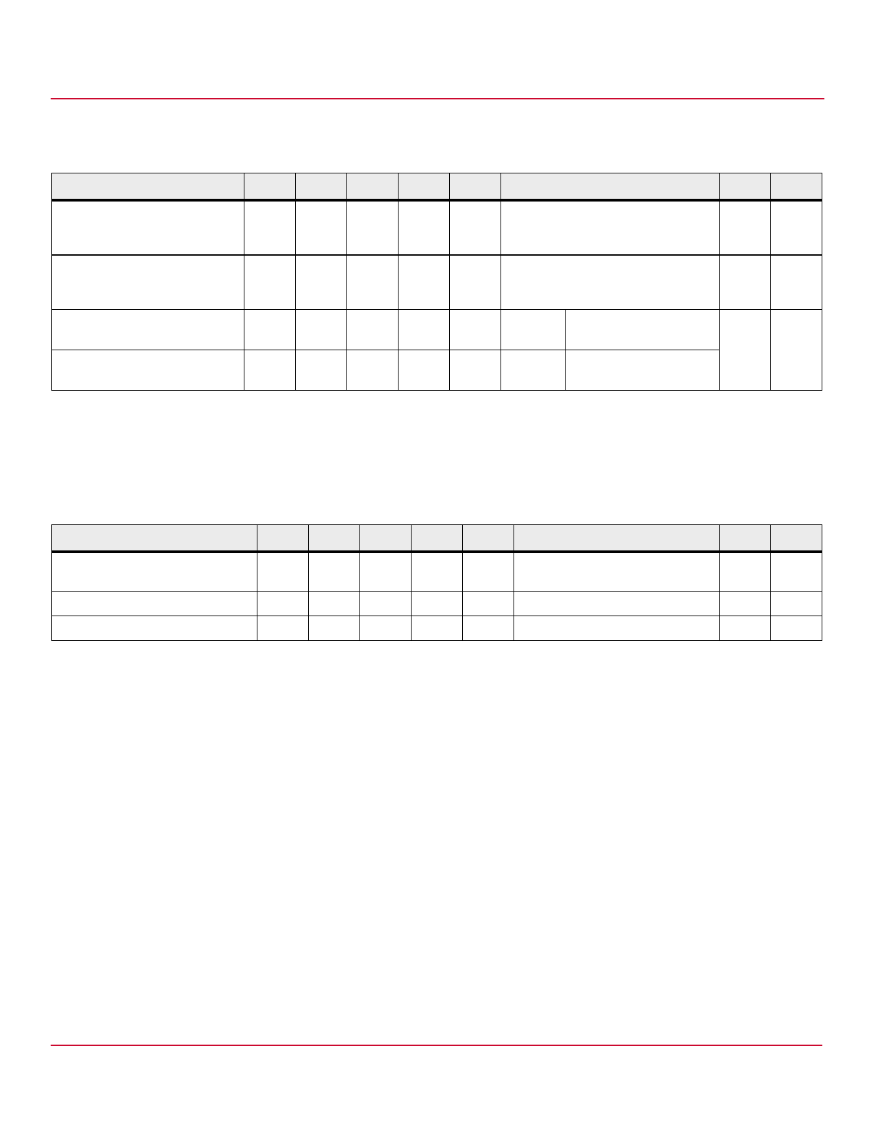
Switching Specifications (AC) for 4-Pin Configuration
Over recommended operating TA = –40°C to 125°C, VCC = 5.0 V unless otherwise specified.
Parameter
Symbol Min. Typ. Max. Units
Test Conditions
Figure Note
Propagation Delay Time to Logic
tPHL
—
Low at Output
2
100
μs Pulse: f = 1 kHz, Duty cycle = 50%,
IF = 4 mA, VCC = 5.0 V, RL=8.2 k,
CL = 15 pF, VTHHL = 1.5V
10
a
Propagation Delay Time to Logic
tPLH
—
High at Output
19
100
μs Pulse: f = 1 kHz, Duty cycle = 50%,
IF = 4 mA, VCC = 5.0 V, RL = 8.2 k,
CL = 15 pF, VTHLH=2.0V
10
a
Common Mode Transient
|CMH| 15
30
— kV/μs IF = 0 mA VCM = 1500 Vp-p, TA = 25°C, 12
a, b
Immunity at Logic High Output
RL = 8.2 k
Common Mode Transient
|CML| 15
30
— kV/μs IF = 10 mA VCM = 1500 Vp-p, TA = 25°C,
Immunity at Logic Low Output
RL = 8.2 k
a. This is in a 4-pin configuration where the VCC and VO pin are shorted together.
b. Common transient immunity in a Logic High level is the maximum tolerable (positive) dVCM/dt on the rising edge of the common mode pulse, VCM, to assure
that the output will remain in a Logic High state (that is, Vo > 2.0V). Common mode transient immunity in a Logic Low level is the maximum tolerable
(negative) dVCM/dt on the falling edge of the common mode pulse signal, VCM to assure that the output will remain in a Logic Low state (that is, Vo < 0.8V).
Package Characteristics
Parameter
Symbol Min. Typ. Max. Units
Test Conditions
Fig. Note
Input-Output Momentary Withstand VISO 4000
—
—
VRMS RH ≤ 50%, t = 1 min., TA = 25°C
b, c
Voltagea
Input-Output Resistance
RI-O
—
1014
—
VI-O = 500 VDC
b
Input-Output Capacitance
CI-O
—
0.6
—
pF f = 1 MHz, VI-O = 0 VDC
b
a. The Input-Output Momentary Withstand Voltage is a dielectric voltage rating that should not be interpreted as an input-output continuous voltage rating.
b. The device is considered a two terminal device: pins 1 and 3 shorted together, and pins 4, 5, and 6 shorted together.
c. In accordance with UL 1577, each optocoupler is proof tested by applying an insulation test voltage ≥ 4800 VRMS for 1 second.
Broadcom
-8-
Share Link: