HCPL-5151-100 データシートの表示(PDF) - Broadcom Corporation
部品番号
コンポーネント説明
メーカー
HCPL-5151-100 Datasheet PDF : 18 Pages
| |||
HCPL-5150 and HCPL-5151,
DLA SMD 5962-04205
Data Sheet
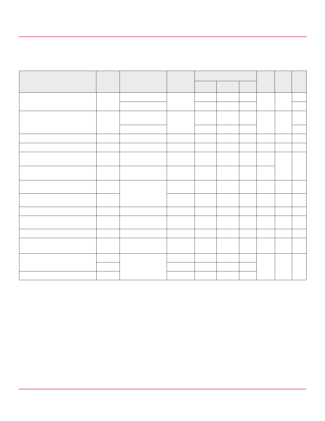
Electrical Specifications (DC)
Over recommended operating conditions (TA = –55°C to +125°C, IF(ON) = 10 mA to 18 mA, VF(OFF) = –3.0V to 0.8V, VCC = 15V to 30V,
VEE = Ground) unless otherwise specified.
Parameter
High Level Output Current
Low Level Output Current
Symbol
IOH
IOL
Test Conditions
Group A
Subgroupsa Min
VO = (VCC – 4V)
1, 2, 3
0.1
VO = (VCC – 15V)
0.5
VO = (VEE + 2.5V)
1, 2, 3
0.1
Limits
Typb
0.4
—
0.6
Unit Fig. Notes
Max
—
A 2, 3, 17 c
—
d
—
A 5, 6, 18 c
High Level Output Voltage
Low Level Output Voltage
High Level Supply Current
Low Level Supply Current
Threshold Input Current
Low to High
Threshold Input Voltage
High to Low
Input Forward Voltage
Temperature Coefficient of Forward
Voltage
Input Reverse Breakdown Voltage
Input Capacitance
UVLO Threshold
UVLO Hysteresis
VO = (VEE + 15V)
VOH
IO = –100 mA
VOL
IO = 100 mA
ICCH
Output Open,
IF = 10 mA to 18 mA
ICCL
Output Open,
VF = –3.0V to +0.8V
IFLH
VFHL
IO = 0 mA,
VO > 5V
VF
ΔVF/ΔTA
BVR
CIN
VUVLO+
VUVLO–
UVLOHYS
IF = 10 mA
IF = 10 mA
IR = 10 µA
f = 1 MHz,
VF = 0 V
VO > 5 V,
IF = 10 mA
1, 2, 3
1, 2, 3
1, 2, 3
0.5
—
—
(VCC – 4) (VCC – 3) —
—
0.4
1.0
—
2.5
5.0
d
V 1, 3, 19 e, f
V 4, 6, 20
mA 7, 8
1, 2, 3
—
2.7
5.0 mA
1, 2, 3
1, 2, 3
1, 2, 3
1, 2, 3
—
2.6
9.0 mA 9, 15,
21
0.8
—
—
V
1.2
1.5
1.8
V
16
—
–1.6
— mV/°C
5
—
—
V
—
80
—
pF
1, 2, 3
1, 2, 3
11.0
12.3 13.5 V 22, 37
9.5
10.7 12.0
—
1.6
—
a. Commercial parts receive 100% testing at 25°C (Subgroups 1 and 9). SMD and Class H parts receive 100% testing at 25°C, 125°C, and –55°C (Subgroups 1 and
9, 2 and 10, 3 and 11, respectively).
b. All typical values at TA = 25°C and VCC – VEE = 30V, unless otherwise noted.
c. Maximum pulse width = 50 μs, maximum duty cycle = 0.5%.
d. Maximum pulse width = 10 μs, maximum duty cycle = 0.2%. This value is intended to allow for component tolerances for designs with IO peak minimum =
0.5A. See Applications Information for additional details on limiting IOH peak.
e. In this test, VOH is measured with a dc load current. When driving capacitive loads, VOH approaches VCC as IOH approaches zero amps.
f. Maximum pulse width = 1 ms, maximum duty cycle = 20%.
Broadcom
-5-
Share Link: 