C106B データシートの表示(PDF) - Unspecified
部品番号
コンポーネント説明
メーカー
C106B Datasheet PDF : 2 Pages
| |||
SEMICONDUCTOR
TECHNICAL DATA
C106B/D/M
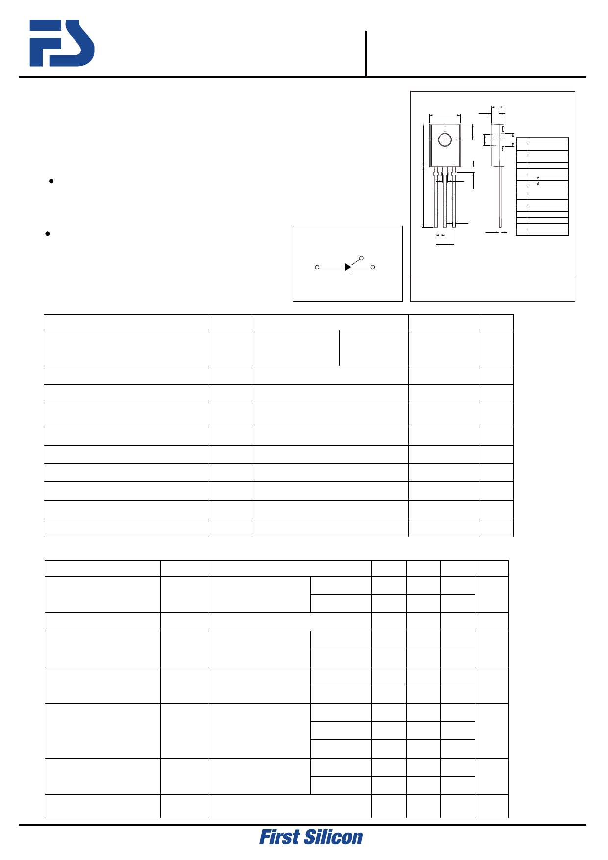
Silicon Planar PNPN Thyristor (4A SCR)
DESCRIPTION
Thyristor in a TO-126F Plastic Package.
FEATURES
The consumption level provide reliable applications,
such as temperature, lighting, speed, etc.
APPLICATIONS
Applied to high Voltage control circuit.
Symbol
Anode
Gate
○
Cathode
Absolute Maximum Ratings(Ta=25℃)
Parameter
Repetitive peak off-state
voltages
RMS on-state current
Average on-state current
Non-repetitive peak on-state
current
I2t for fusing
Peak gate power
Peak Average power
Peak gate current
Junction Temperature
Storage Temperature Range
Symbol
VDRM,
VRRM
IT(RMS)
IT(AV)
ITSM
I 2t
PGM
PG(AV)
IGM
Tj
Tstg
Test Conditions
RGK=1K
TC=-40~110℃
C106B
C106D
C106M
TC=80℃
TC=80℃
1/2 Cycle, Sine Wave,60Hz,
TJ=110℃
t=8.3ms
TC=80℃
TC=80℃
TC=80℃
D
A
E
C
F
B
1 23
H
I
K
L
P
M
G DIM
A
B
C
D
E
F
G
H
I
K
L
M
O
P
MILLIMETERS
8.3 MAX
11.3±0.3
4.15 TYP
3.2±0.2
2 0±0.2
2 8±0.1
3.2±0.1
1.27±0.1
1.40±0.1
15.5±0.2
0.76±0.1
2.28 TYP
4.56±0.1
0 6 MAX
O
1 Cathode
2 ANODE
3 GATE
TO-126F
Rating
Unit
200
400
V
600
4
A
2.55
A
20
A
1.65
A 2S
500
mW
100
mW
0.2
A
-40~+110 ℃
-40~+150 ℃
ELECTRICAL CHARACTERISTICS (Tamb=25℃ unless otherwise specified)
Parameter
Symbol
Repetitive peak off-state IDRM,
current
IRRM
On-state voltage
VTM
Gate trigger current
I GT
Test Conditions
VAK=Rated VDRM or Tc =25℃
VRRM
RGK=1KΩ
Tc=110℃
ITM=4.0A
tp=380uS
VAK=6.0Vdc
RL=100Ω
Tc =25℃
Tc=-40℃
Min Typ
15
35
Gate trigger voltage
VGT
VAK=6.0Vdc
RL=100Ω
Tc =25℃
Tc =-40℃
0.4 0.60
0.5 0.75
Holding current
IH
VAK=12.0Vdc
RGK=1KΩ
Tc =25℃
Tc =-40℃
Tc=110℃
0.19
0.33
0.07
Latching current
Critical rate of rise of
off-state voltage
IL
dv/dt
VAK=12.0Vdc
IG=20mA
Tc =25℃
Tc =-40℃
VAK=Rated VDRM, RGK=1KΩ
TC=110℃
0.20
0.35
8.0
Max
10
100
2.2
200
500
0.80
1.00
3.0
6.0
2.0
5.0
7.0
Unit
μA
V
μA
V
mA
mA
V/us
2015. 02. 06
Revision No : 0
1/2
Share Link: 