LB1860 データシートの表示(PDF) - ON Semiconductor
部品番号
コンポーネント説明
メーカー
LB1860 Datasheet PDF : 8 Pages
| |||
LB1860,1860M,1861,1861M
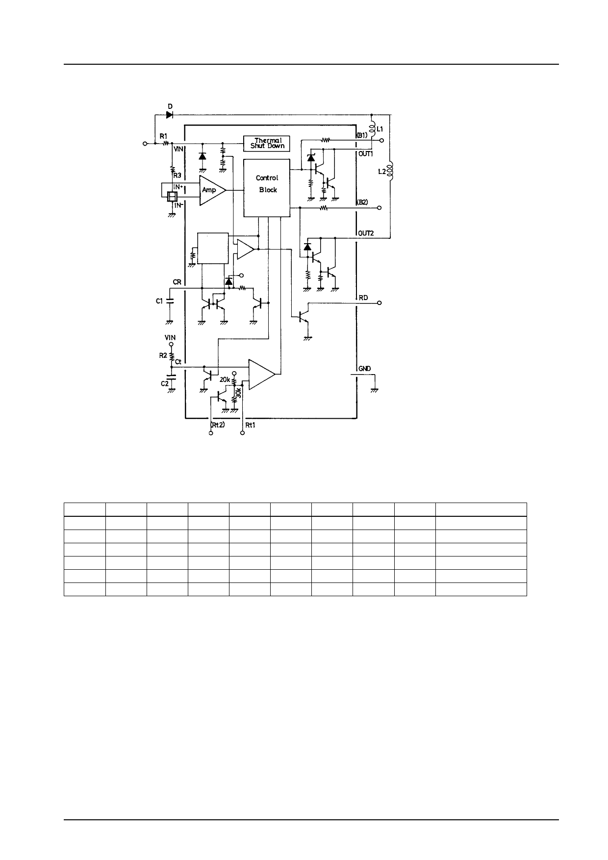
Block Diagram and Application Circuit
Constant
current
circuit
0.47 to 10 µ
Output timing control
( ): MFP14S
Unit (resistance: Ω, capacitance: F)
Truth Table
( ): LB1860M, 1861M
IN+
IN–
Ct
H
L
H
L
H
H
(H)
(L)
—
(L)
(H)
—
—
—
L
—
—
—
Rt1
Rt2
L
—
L
—
—
(H)
—
(H)
H
L
—
—
Figure 1
CR
OUT1
OUT2
RD
L
H
L
L
L
L
H
L
(L)
(H)
(L)
(L)
(L)
(L)
(H)
(L)
L
H
H
L
H
H
H
H
Mode
Full speed
Full speed
(Full speed)
(Full speed)
Low speed
Lock protection
Designer’s Notes
.(1) Variable-speed circuit (Rt and Ct pins) — Refer to the application circuit diagram
The time constant gained by external components C2 and R2 is used to set the length of an ‘off’ operation time period after
phase switching. This means that the variable-speed operations can be performed by changing the ‘on’ operation time of each
. phase through the duty control.
The sawtooth waveform signals are generated by the C2-R2 time constant. The voltage of this signal (Ct pin voltage) increases
from 1.3 V to 4.0 V (Vct) at each phase switching. That is, during this period, the driver becomes inactive (toff), in which
output circuit is turned off.
. If VCC ^ 4.0 V, the driver IC remains active (ton) until the next phase switching. During this period, output circuit is turned on.
. If the active drive time of each phase is assumed to ‘to’, the following relation can be established:
to = toff +
↑
Fixed
constant
ton
↑
Rotation speed
proportional constant
toff = 0.69 c C2 c R2 ........................................ 1
No.3
Share Link: 