LB1860 データシートの表示(PDF) - ON Semiconductor
部品番号
コンポーネント説明
メーカー
LB1860 Datasheet PDF : 8 Pages
| |||
LB1860,1860M,1861,1861M
1 When a fan is rotating, the capacitor is charged at 4 µA (typ) and discharged through the C with pulses according to the
rotational speed.
2 When a fan is locked, no discharge occurs through the C and the C voltage rises, turning OFF the output at 0.8 × VIN.
3 When the output is turned OFF, discharge occurs through the C at 0.5 µA (typ). If the lock is not released when the C voltage
drops to VTH2, the capacitor is charged to VTH1 again. (At this moment, the output is turned ON.) These operations 2 and
3 repeated at a cycle of approximately ton : toff = 1:6 protect a motor.
4 If the lock is released when the C voltage drops to VTH2, the output is turned ON, starting rotation.
.(6) Rotation detect signal (RD pin)
Open collector output (Drive mode: ‘‘L’’, Stop mode: ‘‘H’’)
(7) Radio noise reducing (Pins B1, B2)
. Base pin of Darlington connection output transistor
. If radio noises need to be processed properly, the following actions should be taken:
1 Connect a capacitor of 0.01 µ to 0.1 µF between B1 and B2.
2 Connect a capacitor of 0.001 µ to 0.01 µF between OUT and B.
If output causes oscillation, add a resistor of 200 Ω to 1 kΩ in series with a capacitor.
.(8) Thermal shutdown function
Shutdown the driver output in case of coil short-circuiting and abnormal IC heating.
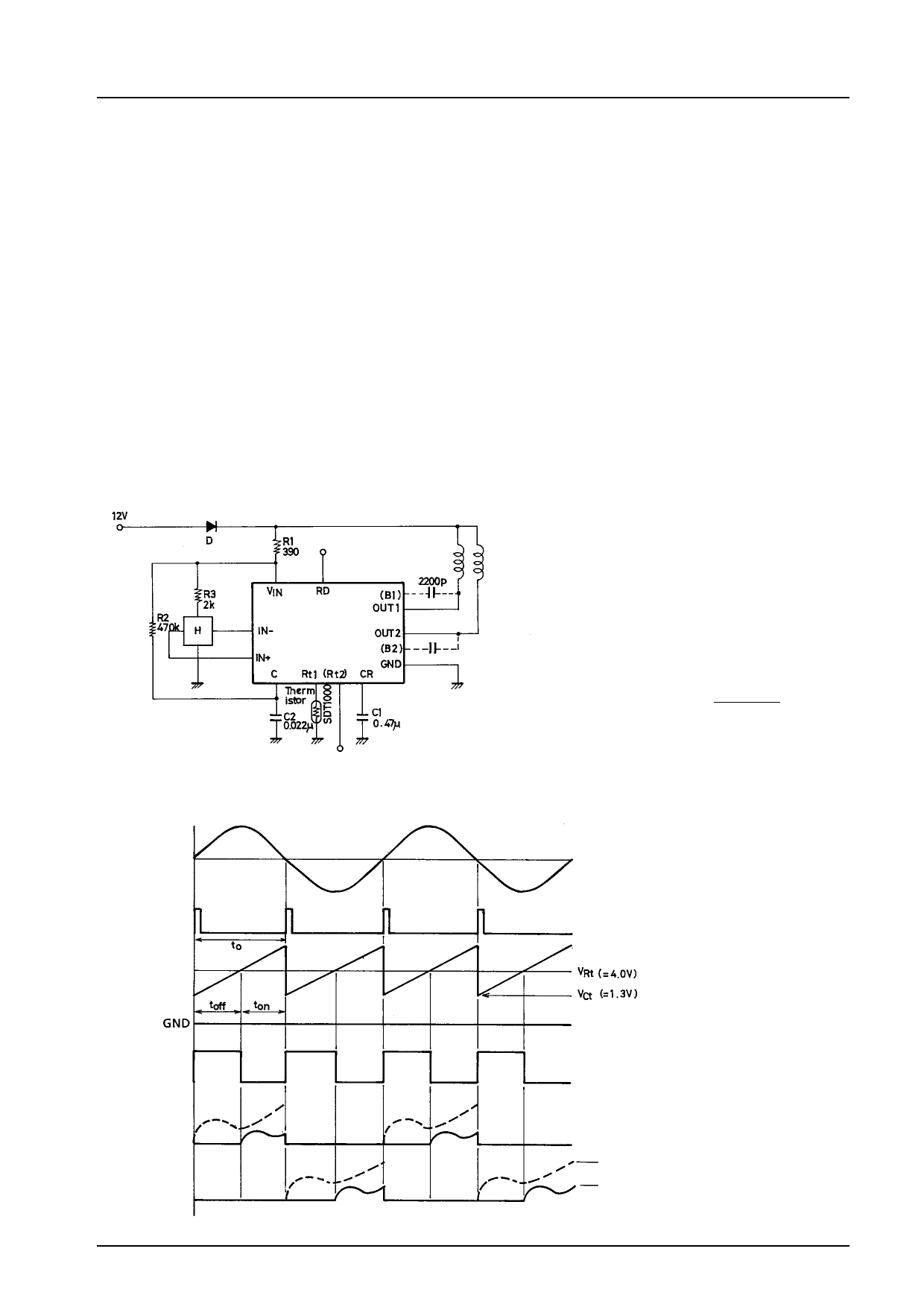
Thermistor-controlled Application Circuit Example
Figure 2
Output Timing Chart
Noise elimination
capacitor
Use of a thermistor enables motor speed to
be sensitive to the operating ambient
temperature.
The Rt pin voltage at Ta = 20 °C has
1.42 ms of ‘toff’ as calculated in expression
4 with the application constant of Figure 2.
However, the Rt pin voltage at Ta = 40 °C
is reduced into less than the Vct (= 1.3 V)
level, which results in a 0 of ‘toff’. This
means the 100% duty.
t = –C2 c R2 c 1n (VIN – VRt) ............. 4
VIN – VCt
( ): MFP14S
Unit (resistance: Ω, capacitance: F)
Hall input
Discharge pulse
Ct voltage
Output ‘off’ signal
OUT1 current
OUT2 current
All-phase ON waveform
Control output waveform
Figure 3
No.5
Share Link: 