ACPL-P484-060E データシートの表示(PDF) - Broadcom Corporation
部品番号
コンポーネント説明
メーカー
ACPL-P484-060E
Broadcom Corporation

ACPL-P484-060E Datasheet PDF : 13 Pages
| |||
ACPL-M484/P484/W484
Positive Logic High CMR Intelligent Power Module and
Gate Drive Interface Optocoupler
Data Sheet
Description
The ACPL-M484/P484/W484 fast-speed optocoupler contains a
AlGaAs LED and photo detector with built-in Schmitt trigger to
provide logic-compatible waveforms, eliminating the need for
additional wave shaping. The totem pole output eliminates the
need for a pull-up resistor and allows for direct drive Intelligent
Power Module or gate drive. Minimized propagation delay
difference between devices makes these optocouplers
excellent solutions for improving inverter efficiency through
reduced switching dead time.
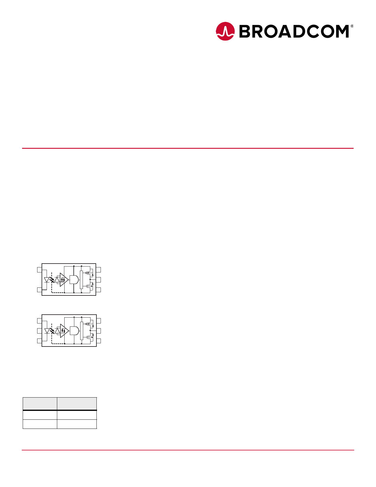
Functional Diagram
Anode 1
ACPL-M484
Cathode 3
SHIELD
6 VCC
5 VO
4 Ground
ACPL-P484 and ACPL-W484
Anode 1
6 VCC
N.C. 2
5 VO
Cathode 3
SHIELD
4 Ground
Note: A 0.1 μF bypass capacitor must be connected between
pins 4 and 6. Truth Table Guaranteed: VCC from 4.5V to 30V.
Truth Table (Non-Inverting Logic)
LED
V0
ON
HIGH
OFF
LOW
Features
Positive output type (totem pole output)
Truth Table Guaranteed: VCC from 4.5V to 30V
Performance Specified for Common IPM Applications Over
Industrial Temperature Range
Short Maximum Propagation Delays
Minimized Pulse Width Distortion (PWD)
Very High Common Mode Rejection (CMR)
Hysteresis
Available in SO-5 (ACPL-M484) and Stretched SO-6
package (ACPCL-P484/W484)
Package Clearance/Creepage at 8 mm (ACPL-W484)
Safety Approval:
— UL Recognized with 5000VRMS (ACPL-W484) for 1
minute per UL1577.
— CSA Approved.
— IEC/EN/DIN EN 60747-5-5 Approved with VIORM =
567Vpeak for ACPL-M484 and VIORM = 891Vpeak for
ACPL-P484 and VIORM = 1140Vpeak for ACPL-W484,
under option 060.
Specifications
Wide Operating Temperature Range: –40°C to +105°C
Maximum Propagation Delay tPHL/tPLH = 150 ns/120 ns
Maximum Pulse Width Distortion (PWD) = 90 ns
Propagation Delay Difference: Min/Max = –130 ns/+130 ns
Wide Operating VCC Range: 4.5V to 30V
30 kV/μs Minimum Common Mode Rejection (CMR) at
VCM = 1000V
CAUTION
It is advised that normal static precautions be
taken in handling and assembly of this
component to prevent damage and/or
degradation which may be induced by ESD.
Broadcom
-1-
Share Link: