M54676E データシートの表示(PDF) - MITSUBISHI ELECTRIC
部品番号
コンポーネント説明
メーカー
M54676E Datasheet PDF : 5 Pages
| |||
MITSUBISHI <CONTROL / DRIVER IC>
M54676P
2-PHASE STEPPER MOTOR DRIVER
PRECAUTIONS FOR USE
Sequence of supply voltage (VM and Vcc5) and logic
input voltage
The VM voltage should be the maximum voltage among all volt-
ages applied to this IC. If no voltage is applied to VM and 5V
voltage is applied to Vcc5 pin and logic input pin, leak current flows
from Vcc5 pin and logic input pin to VM through a surge protection
diode.
Wiring on the board
Current is controlled by flowing output current to the current
sensing resistor (1 ohmlevel) to measure the voltage fall.
The output current performs the chopping operation at high speed.
Therefore, wiring to flow current and to connect the high-
impedance input pin (Vref) should be conducted carefully not to
cause a cross talk.
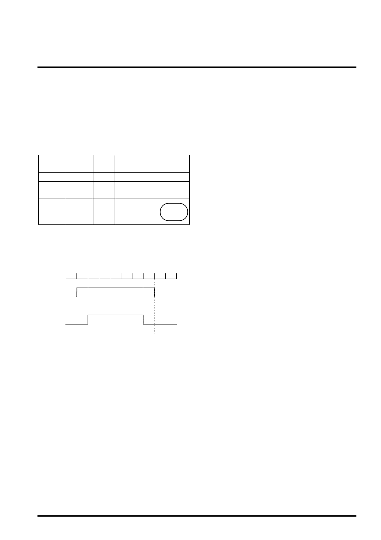
VM
12V
12V
0V
(Open)
Vcc5
5V
0V
(Open)
5V
Logic
input
Mode
5V,0V Normal operation mode
5V,0V
Standby mode (No current flows to
logic input pin and Vcc pin.)
5V,0V
Leak current flows
from Vcc5 pin and
logic input pin to
Prohibited
VM pin.
Sequence
After the VM voltage rises, set the Vcc5 power supply voltage and
logic input voltage. Similarly, after Vcc5 supply voltage and logic
input voltage rise, raise the VM supply voltage.
Time
VM
Vcc5
and
logic input
Thermal shutdown function
The circuit board on which this IC is mounted is designed to realize
low impedance between power supply and output pin. Therefore, it
is desirable to take a safe measure such as fixing a fuse to avoid
such a situation that the board is damaged by a fire when output
pin is internally short-circuited by excessive surge voltage applied
externally by accident (or when the TSD function is damaged).
Thermal loss
In case that conditions for use (regarding supply voltage and
output current) or a board used is changed, sufficient thermal
evaluation should be conducted and design should be worked out
to leave a margin for thermal loss. The higher the chopping
frequency is, the larger switching loss within the IC becomes.
Share Link: 