FAN7621SSJX データシートの表示(PDF) - ON Semiconductor
部品番号
コンポーネント説明
メーカー
FAN7621SSJX Datasheet PDF : 14 Pages
| |||
Functional Description
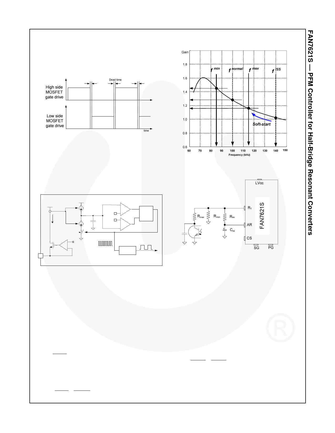
1. Basic Operation: FAN7621S is designed to drive
high-side and low-side MOSFETs complementarily with
50% duty cycle. A fixed dead time of 350ns is introduced
between consecutive transitions, as shown in Figure 15.
Figure 15. MOSFETs Gate Drive Signal
2. Internal Oscillator: FAN7621S employs a current-
controlled oscillator, as shown in Figure 16. Internally,
the voltage of RT pin is regulated at 2V and the charging /
discharging current for the oscillator capacitor, CT, is
obtained by copying the current flowing out of RT pin
(ICTC) using a current mirror. Therefore, the switching
frequency increases as ICTC increases.
Figure 17. Resonant Converter Typical Gain Curve
V REF
I CTC
I CTC 2I CTC
RT
8
+
- 2V
+
3V
-
1V
+
CT
-
SQ
R -Q
F /F
C oun ter
(1/4)
G ate drive
Figure 18. Frequency Control Circuit
Figure 16. Current Controlled Oscillator
3. Frequency Setting: Figure 17 shows the typical
voltage gain curve of a resonant converter, where the
gain is inversely proportional to the switching frequency
in the ZVS region. The output voltage can be regulated
by modulating the switching frequency. Figure 18 shows
the typical circuit configuration for RT pin, where the opto-
coupler transistor is connected to the RT pin to modulate
the switching frequency.
The minimum switching frequency is determined as:
f min = 5.2kΩ ×100 (kHz)
(1)
Rmin
Assuming the saturation voltage of the opto-coupler
transistor is 0.2V, the maximum switching frequency is
determined as:
f max = (5.2kΩ + 4.68kΩ ) ×100(kHz)
(2)
Rmin
Rmax
To prevent excessive inrush current and overshoot of
output voltage during startup, increase the voltage gain
of the resonant converter progressively. Since the
voltage gain of the resonant converter is inversely
proportional to the switching frequency, the soft-start is
implemented by sweeping down the switching frequency
from an initial high frequency (f I S S ) until the output
voltage is established. The soft-start circuit is made by
connecting R-C series network on the RT pin, as shown
in Figure 18. FAN7621S also has an internal soft-start of
3ms to reduce the current overshoot during the initial
cycles, which adds 40kHz to the initial frequency of the
external soft-start circuit, as shown in Figure 19. The
initial frequency of the soft-start is given as:
f ISS = (5.2kΩ + 5.2kΩ ) ×100 + 40 (kHz)
(3)
Rmin
RSS
It is typical to set the initial (soft-start) frequency two ~
three times the resonant frequency (fO) of the resonant
network.
© 2009 Fairchild Semiconductor Corporation
FAN7621S • Rev. 1.0.1
9
www.fairchildsemi.com
Share Link: 