BCW72LT1 データシートの表示(PDF) - Leshan Radio Company
部品番号
コンポーネント説明
メーカー
BCW72LT1 Datasheet PDF : 6 Pages
| |||
LESHAN RADIO COMPANY, LTD.
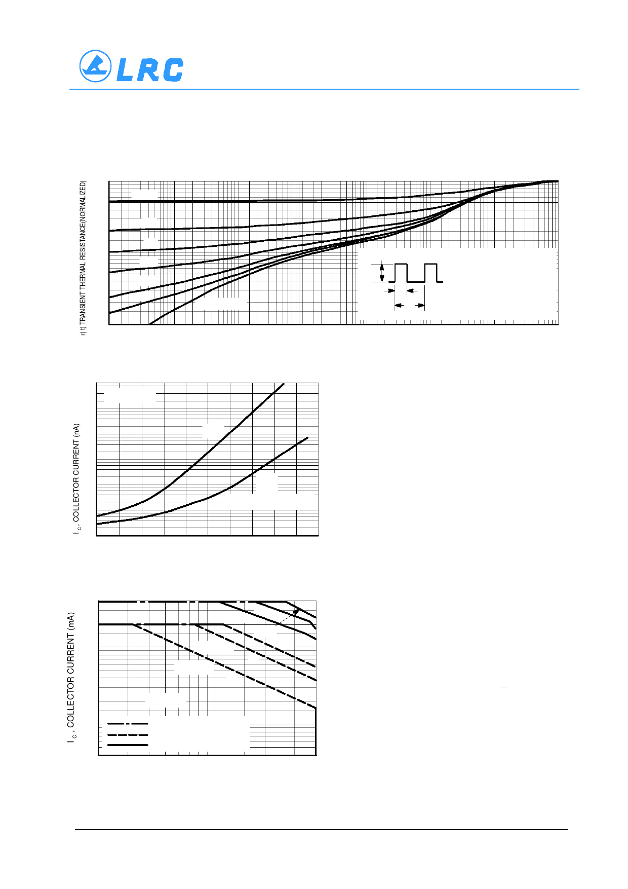
BCW72LT1
1.0
0.7
0.5
D = 0.5
0.3
0.2
0.2
0.1
0.07
0.05
0.03
0.02
0.01
0.01
0.1
0.05
0.02
0.01
SINGLE PULSE
0.02 0.05 0.1 0.2
0.5 1.0 2.0
FIGURE 19A
P(pk)
t1
t2
DUTY CYCLE, D = t 1 / t 2
D CURVES APPLY FOR POWER
PULSE TRAIN SHOWN
READ TIME AT t (SEE AN–569)
1
Z θJA(t) = r(t) • RθJA
T J(pk) – T A = P (pk) Z θJA(t)
5.0 10 20
50 100 200 500 1.0k 2.0k
t, TIME (ms)
Figure 19. Thermal Response
5.0k 10k 20k
50k 100k
104
103
102
101
100
10–1
10–2
–4
V CC = 30 Vdc
I CEO
I
CBO
AND
I CEX @ V BE(off) = 3.0 Vdc
–2
0 +20 +40 +60 +80 +100 +120 +140 +160
T J , JUNCTION TEMPERATURE (°C)
Figure 19A.
DESIGN NOTE: USE OF THERMAL RESPONSE DATA
A train of periodical power pulses can be represented by the
model as shown in Figure 19A. Using the model and the device
thermal response the normalized effective transient thermal re-
sistance of Figure 19 was calculated for various duty cycles.
To find Z θJA(t) , multiply the value obtained from Figure 19 by
the steady state value R θJA .
Example:
The MPS3904 is dissipating 2.0 watts peak under the follow-
ing conditions:
t 1 = 1.0 ms, t 2 = 5.0 ms. (D = 0.2)
Using Figure 19 at a pulse width of 1.0 ms and D = 0.2, the
reading of r(t) is 0.22.
The peak rise in junction temperature is therefore
∆T = r(t) x P (pk) x R θJA = 0.22 x 2.0 x 200 = 88°C.
For more information, see AN–569.
400
200
100
60
40
20
10
6.0
4.0
2.0
1.0 ms 100µs
T C = 25°C
T A = 25°C
dc
10µs
1.0 s
dc
T J = 150°C
CURRENT LIMIT
THERMAL LIMIT
SECOND BREAKDOWN LIMIT
4.0
6.0 8.0 10
20
The safe operating area curves indicate I C –V CE limits of
the transistor that must be observed for reliable operation.
Collector load lines for specific circuits must fall below the
limits indicated by the applicable curve.
The data of Figure 20 is based upon T J(pk) = 150°C; T C or
T A is variable depending upon conditions. Pulse curves are
valid for duty cycles to 10% provided T J(pk) <150°C. T J(pk)
may be calculated from the data in Figure 19. At high case
or ambient temperatures, thermal limitations will reduce the
power that can be handled to values less than the limitations
imposed by second breakdown.
40
V CE , COLLECTOR–EMITTER VOLTAGE (VOLTS)
Figure 20.
M14–6/6
Share Link: 