GMF05LC-HSF データシートの表示(PDF) - Vishay Semiconductors
部品番号
コンポーネント説明
メーカー
GMF05LC-HSF Datasheet PDF : 7 Pages
| |||
www.vishay.com
GMF05LC-HSF
Vishay Semiconductors
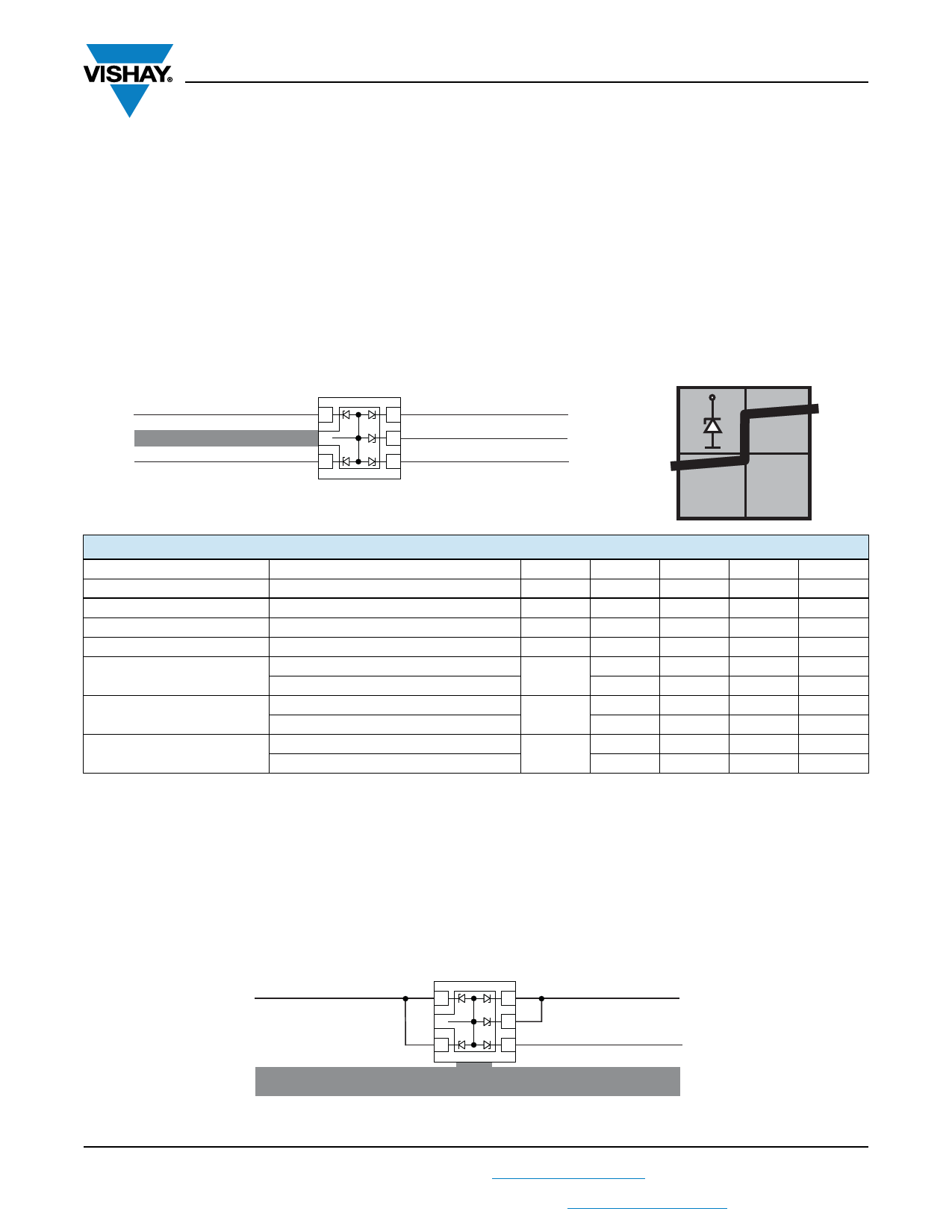
BiAs-MODE (5-line bidirectional asymmetrical protection mode)
With the GMF05LC-HSF up to 5 signal- or data-lines (L1 to L5) can be protected against voltage transients. With pin 2
connected to ground and pin 1; pin 3 up to pin 6 connected to a signal- or data-line which has to be protected. As long as the
voltage level on the data- or signal-line is between 0 V (ground level) and the specified maximum reverse working voltage (VRWM)
the protection diode between data-line and ground offer a high isolation to the ground line. The protection device behaves like
an open switch.
As soon as any positive transient voltage signal exceeds the break through voltage level of the protection diode, the diode
becomes conductive and shorts the transient current to ground. Now the protection device behaves like a closed switch. The
clamping voltage (VC) is defined by the breakthrough voltage (VBR) level plus the voltage drop at the series impedance
(resistance and inductance) of the protection device.
Any negative transient signal will be clamped accordingly. The negative transient current is flowing in the forward direction of
the protection diode. The low forward voltage (VF) clamps the negative transient close to the ground level.
Due to the different clamping levels in forward and reverse direction the GMF05LC-HSF clamping behavior is bidirectional and
asymmetrical (BiAs).
L1
1
5
L5
Ground
2
4
L4
L2
3
3
L3
20739
BiAs
ELECTRICAL CHARACTERISTICS GMF05LC-HSF
PARAMETER
TEST CONDITIONS/REMARKS
SYMBOL MIN.
TYP.
MAX.
UNIT
Protection paths
Number of lines which can be protected
Nchannel
-
-
5
Reverse stand-off voltage
at IR = 1 μA
VRWM
-
-
5
Reverse current
at VR = VRWM = 5 V
IR
-
0.01
0.1
Reverse breakdown voltage
at IR = 1 mA
VBR
6
-
8
Reverse clamping voltage
at IPP = 1 A acc. IEC 61000-4-5
at IPP = IPPM = 5 A acc. IEC 61000-4-5
VC
-
8
9.5
-
11.5
12.5
Forward clamping voltage
at IF = 1 A acc. IEC 61000-4-5
at IPP = IPPM = 5 A acc. IEC 61000-4-5
VF
-
-
1.5
2
3.1
4
Capacitance
at VR = 0 V; f = 1 MHz
at VR = 2.5 V; f = 1 MHz
-
43
50
CD
-
25
-
Note
• Ratings at 25 °C ambient temperature, unless otherwise specified. BiAs mode: each input (pin 1, 2, 3, to 6) to ground (pin 2).
lines
V
μA
V
V
V
V
V
pF
pF
If a higher surge current or peak pulse current (IPP) is needed, some protection diodes in the GMF05LC-HSF can also be used
in parallel in order to “multiply” the performance.
If two diodes are switched in parallel you get
• double surge power = double peak pulse current (2 x IPPM)
• half of the line inductance = reduced clamping voltage
• half of the line resistance = reduced clamping voltage
• double line capacitance (2 x CD)
• double reverse leakage current (2 x IR)
L1
1
6
L2
2
5
3
4
L3
Ground
20740
Rev. 1.6, 04-Jan-2019
2
Document Number: 81200
For technical questions, contact: ESDprotection@vishay.com
THIS DOCUMENT IS SUBJECT TO CHANGE WITHOUT NOTICE. THE PRODUCTS DESCRIBED HEREIN AND THIS DOCUMENT
ARE SUBJECT TO SPECIFIC DISCLAIMERS, SET FORTH AT www.vishay.com/doc?91000
Share Link: 