M24C01(2000) データシートの表示(PDF) - STMicroelectronics
部品番号
コンポーネント説明
メーカー
M24C01 Datasheet PDF : 20 Pages
| |||
M24C16, M24C08, M24C04, M24C02, M24C01
Table 5A. DC Characteristics
(TA = 0 to 70 °C, or –40 to 85 °C; VCC = 4.5 to 5.5 V or 2.5 to 5.5 V)
(TA = 0 to 70 °C, or –40 to 85 °C; VCC = 1.8 to 3.6 V)
Symbol
Parameter
Test Condition
ILI
Input Leakage Current
(SCL, SDA)
0 V ≤ VIN ≤ VCC
ILO Output Leakage Current
0 V ≤ VOUT ≤ VCC, SDA in Hi-Z
VCC=5V, fc=400kHz (rise/fall time < 30ns)
ICC Supply Current
-W series: VCC =2.5V, fc=400kHz (rise/fall time < 30ns)
-R series: VCC =1.8V, fc=400kHz (rise/fall time < 30ns)
ICC1
Supply Current
(Stand-by)
-W series:
-R series:
VIN = VSS or VCC , VCC = 5 V
VIN = VSS or VCC , VCC = 2.5 V
VIN = VSS or VCC , VCC = 1.8 V
VIL
Input Low Voltage
(E0, E1, E2, SCL, SDA)
VIH
Input High Voltage
(E0, E1, E2, SCL, SDA)
VIL Input Low Voltage (WC)
VIH Input High Voltage (WC)
VOL
Output Low
Voltage
Note: 1. This is preliminary data.
-W series:
-R series:
IOL = 3 mA, VCC = 5 V
IOL = 2.1 mA, VCC = 2.5 V
IOL = 0.7 mA, VCC = 1.8 V
Min.
– 0.3
0.7VCC
– 0.3
0.7VCC
Max. Unit
± 2 µA
± 2 µA
2
mA
1
mA
0.81 mA
1
µA
0.5
µA
0.11 µA
0.3 VCC V
VCC+1 V
0.5
V
VCC+1 V
0.4
V
0.4
V
0.21
V
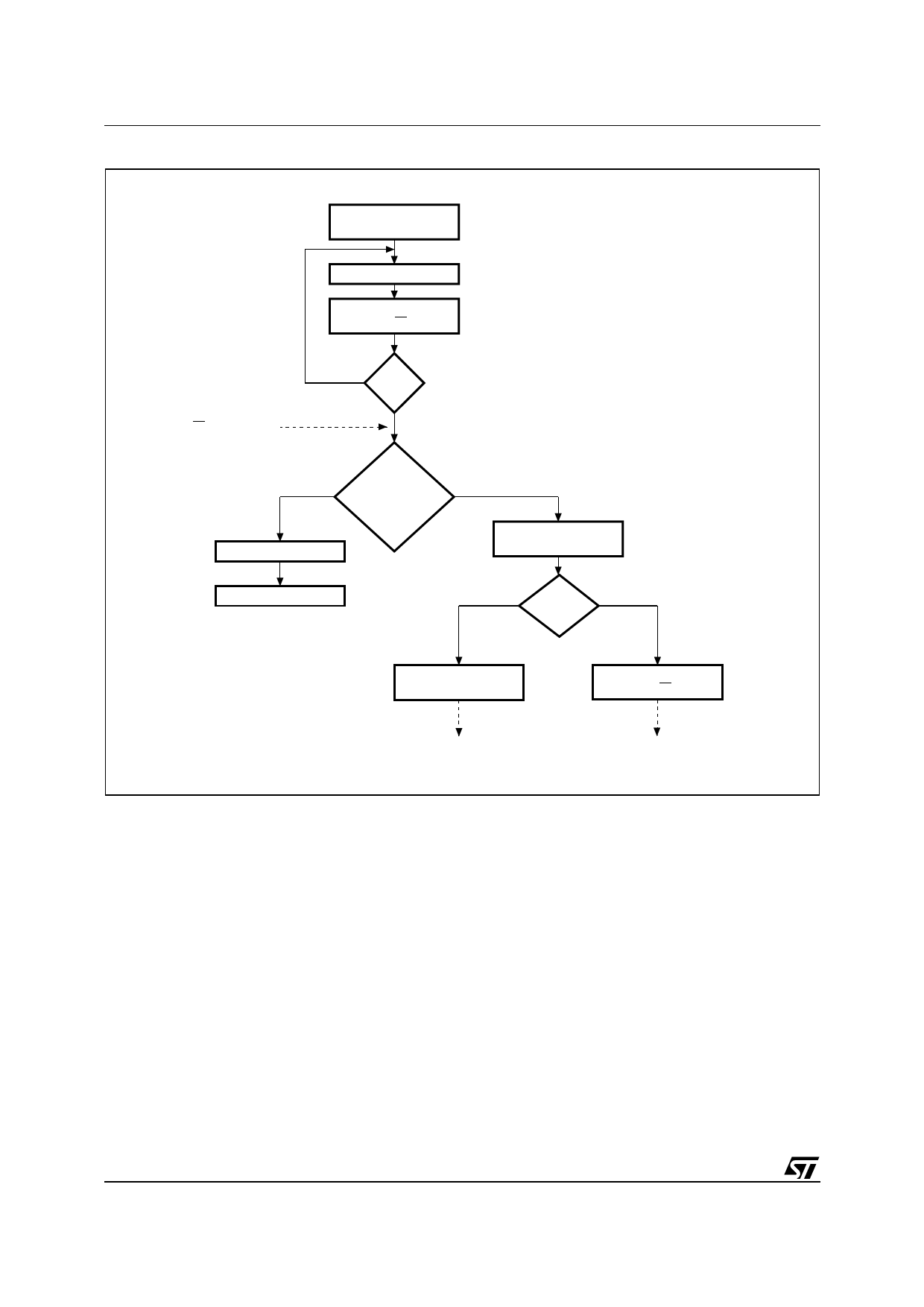
Current Address Read
The device has an internal address counter which
is incremented each time a byte is read. For the
Current Address Read mode, following a START
condition, the master sends a Device Select Code
with the RW bit set to ‘1’. The memory
acknowledges this, and outputs the byte
addressed by the internal address counter. The
counter is then incremented. The master
terminates the transfer with a STOP condition, as
shown in Figure 8, without acknowledging the byte
output.
Sequential Read
This mode can be initiated with either a Current
Address Read or a Random Address Read. The
master does acknowledge the data byte output in
this case, and the memory continues to output the
next byte in sequence. To terminate the stream of
bytes, the master must not acknowledge the last
byte output, and must generate a STOP condition.
The output data comes from consecutive
addresses, with the internal address counter
automatically incremented after each byte output.
After the last memory address, the address
counter ‘rolls-over’ and the memory continues to
output data from memory address 00h.
Acknowledge in Read Mode
In all read modes, the memory waits, after each
byte read, for an acknowledgment during the 9th
bit time. If the master does not pull the SDA line
low during this time, the memory terminates the
data transfer and switches to its stand-by state.
10/20
Share Link: 