M24C01(2000) гғҮгғјгӮҝгӮ·гғјгғҲгҒ®иЎЁзӨәпјҲPDFпјү - STMicroelectronics
йғЁе“Ғз•ӘеҸ·
гӮігғігғқгғјгғҚгғігғҲиӘ¬жҳҺ
гғЎгғјгӮ«гғј
M24C01 Datasheet PDF : 20 Pages
| |||
M24C16, M24C08, M24C04, M24C02, M24C01
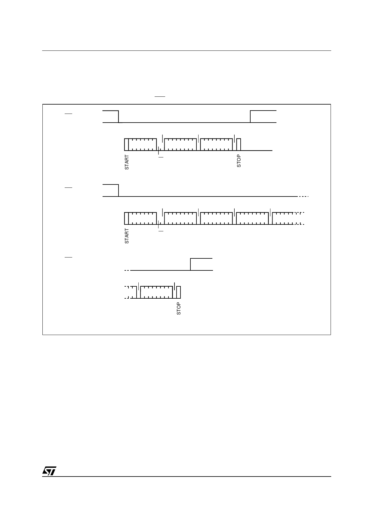
Figure 8. Read Mode Sequences
CURRENT
ADDRESS
READ
ACK
NO ACK
DEV SEL
DATA OUT
R/W
RANDOM
ADDRESS
READ
ACK
ACK
ACK
NO ACK
DEV SEL *
BYTE ADDR
DEV SEL *
DATA OUT
R/W
R/W
SEQUENTIAL
CURRENT
READ
SEQUENTIAL
RANDOM
READ
ACK
ACK
DEV SEL
DATA OUT 1
R/W
ACK
NO ACK
DATA OUT N
ACK
ACK
ACK
ACK
DEV SEL *
BYTE ADDR
DEV SEL *
DATA OUT 1
R/W
R/W
ACK
NO ACK
DATA OUT N
AI01942
Note: 1. The seven most significant bits of the Device Select Code of a Random Read (in the 1st and 3rd bytes) must be identical.
The sequence, as shown in Figure 7, is:
вҖ“ Initial condition: a Write is in progress.
вҖ“ Step 1: the master issues a START condition
followed by a Device Select Code (the first byte
of the new instruction).
вҖ“ Step 2: if the memory is busy with the internal
write cycle, no Ack will be returned and the
master goes back to Step 1. If the memory has
terminated the internal write cycle, it responds
with an Ack, indicating that the memory is ready
to receive the second part of the next instruction
(the first byte of this instruction having been sent
during Step 1).
Read Operations
Read operations are performed independently of
the state of the WC pin.
Random Address Read
A dummy write is performed to load the address
into the address counter, as shown in Figure 8.
Then, without sending a STOP condition, the
master sends another START condition, and
repeats the Device Select Code, with the RW bit
set to вҖҳ1вҖҷ. The memory acknowledges this, and
outputs the contents of the addressed byte. The
master must not acknowledge the byte output, and
terminates the transfer with a STOP condition.
9/20
Share Link: 