CMT2210LW データシートの表示(PDF) - Unspecified
部品番号
コンポーネント説明
メーカー
CMT2210LW Datasheet PDF : 20 Pages
| |||
CMT2210LW
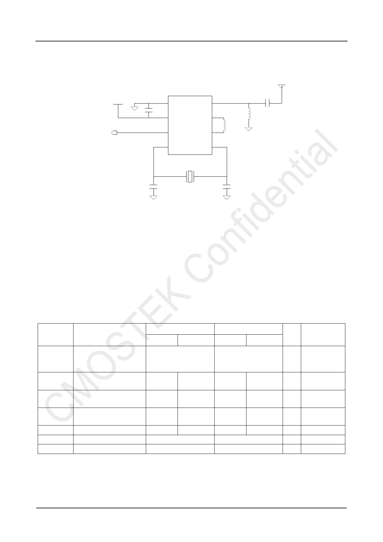
4. Typical Application Schematic
VDD
DOUT
1
C0
2
GND
VDD
3 DOUT
4 XOUT
RFIN 8
VCON 7
L2
VCOP 6
XIN 5
X1
C2
C3
ANT
C1
L1
Figure 9. Typical Application Schematic
Notes:
1. The general layout guidelines are listed below. For more design details, please refer to “AN107 CMT221x Schematic and
PCB Layout Design Guideline”.
Use as much continuous ground plane metallization as possible.
Use as many grounding vias (especially near to the GND pins) as possible to minimize series parasitic inductance
between the ground pour and the GND pins.
Avoid using long and/or thin transmission lines to connect the components.
Place C0 as close to the CMT2210LW as possible for better filtering.
2. The table below shows the BOM of typical application for 50 Ω antennas and other common used antennas in the market.
Table 7. BOM of 315/433.92 MHz Typical Application
Designator
U1
X1
L1
L2
C1
C0
C2, C3
Descriptions
CMT2210LW, low-cost
315/433.92 MHz OOK
stand-alone receiver
±20 ppm, SMD32*25 mm,
crystal
±5%, 0603 multi-layer chip
inductor
±5%, 0603 multi-layer chip
inductor
±0.25 pF, 0402 NP0, 50 V
±20%, 0402 X7R, 25 V
±5%, 0402 NP0, 50 V
Value (Match to 50Ω ANT) Value (Common Used ANT)
315 MHz 433.92 MHz 315 MHz 433.92 MHz
-
-
18.8744
26
33
27
33
22
5.6
3.3
0.1
27
18.8744
26
68
33
33
22
4.3
2.7
0.1
27
Unit
-
MHz
nH
nH
pF
uF
pF
Manufacturer
CMOSTEK
EPSON
Murata LQG18
Murata LQG18
Murata GRM15
Murata GRM15
Murata GRM15
Rev 0.8 | Page 9/20
www.hoperf.com
Share Link: 