IRS2108 データシートの表示(PDF) - International Rectifier
部品番号
コンポーネント説明
メーカー
IRS2108 Datasheet PDF : 25 Pages
| |||
Data Sheet No. PD60260
IRS2108/IRS21084(S)PbF
Features
HALF-BRIDGE DRIVER
• Floating channel designed for bootstrap operation
• Fully operational to +600 V
• Tolerant to negative transient voltage, dV/dt
immune
• Gate drive supply range from 10 V to 20 V
• Undervoltage lockout for both channels
• 3.3 V, 5 V, and 15 V input logic compatible
• Cross-conduction prevention logic
• Matched propagation delay for both channels
• High-side output in phase with HIN input
• Low-side output out of phase with LIN input
• Logic and power ground +/- 5 V offset
• Internal 540 ns deadtime, and programmable up
to 5 µs with one external RDT resistor (IRS21084)
••
Lower
RoHS
di/dt gate
compliant
driver
for
better
noise
immunity
Packages
8-Lead PDIP
14-Lead PDIP
8-Lead SOIC
14-Lead SOIC
Description
The IRS2108/IRS21084 are high volt-
age, high speed power MOSFET and
IGBT drivers with dependent high- and
low-side referenced output channels.
Proprietary HVIC and latch immune
CMOS technologies enable ruggedized
monolithic construction. The logic input
is compatible with standard CMOS or
LSTTL output, down to 3.3 V logic. The
output drivers feature a high pulse cur-
Feature Comparison
Part
Input
logic
2106/2301
21064
2108
21084
2109/2302
21094
2304
HIN/LIN
HIN/LIN
IN/SD
HIN/LIN
Cross-
conduction
prevention
logic
no
yes
yes
yes
Deadtime
(ns)
none
Internal 540
Programmable 540 - 5000
Internal 540
Programmable 540 - 5000
Internal 100
Ground Pins
COM
VSS/COM
COM
VSS/COM
COM
VSS/COM
COM
ton/toff
(ns)
220/200
220/200
750/200
160/140
rent buffer stage designed for minimum driver cross-conduction. The floating channel can be used to drive an
N-channel power MOSFET or IGBT in the high-side configuration which operates up to 600 V.
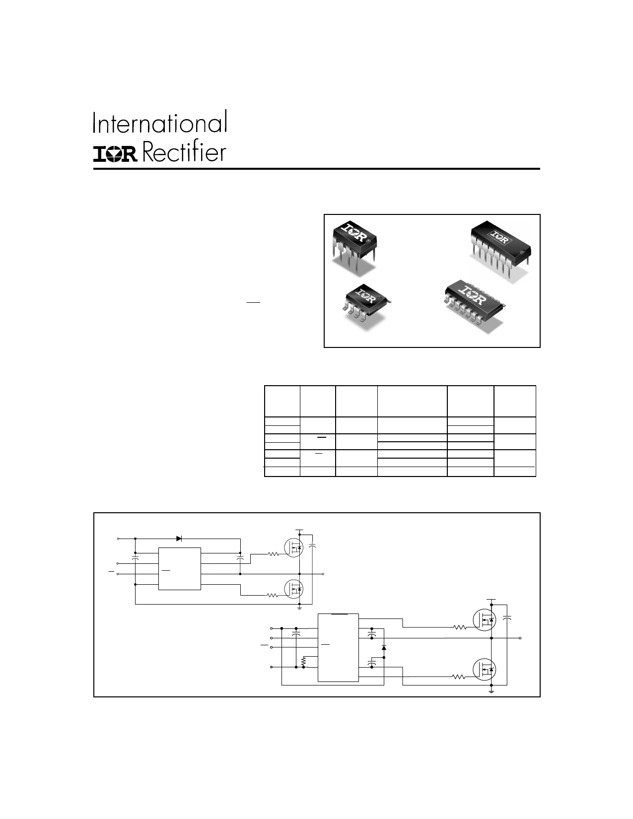
Typical Connection
VCC
VCC
VB
HIN
HIN
HO
LIN
LIN
VS
COM
LO
up to 600 V
TO
LOAD
IRS2108
VCC
HIN
LIN
(Refer to Lead Assignments for correct pin
configuration). These diagrams show
electrical connections only. Please refer to
VSS
our Application Notes and DesignTips for
proper circuit board layout.
HO
VCC
VB
HIN
VS
LIN
DT
VSS
COM
RDT
LO
IRS21084
up to 600 V
TO
LOAD
www.irf.com
1
Share Link: 