MB4S データシートの表示(PDF) - Shanghai Leiditech Electronic Technology Co., Ltd
部品番号
コンポーネント説明
メーカー
MB4S Datasheet PDF : 3 Pages
| |||
Features
● Low forward voltage drop
● Ideal for automated placement
● Glass Passivated chip junction
● Low profile space
● Low leakage current
● High forward surge capability
● High temperature soldering:
260℃/10 seconds at terminals
● Component in accordance to
RoHS 2011/65/EU and WEEE 2002/96/EC
Mechanical Date
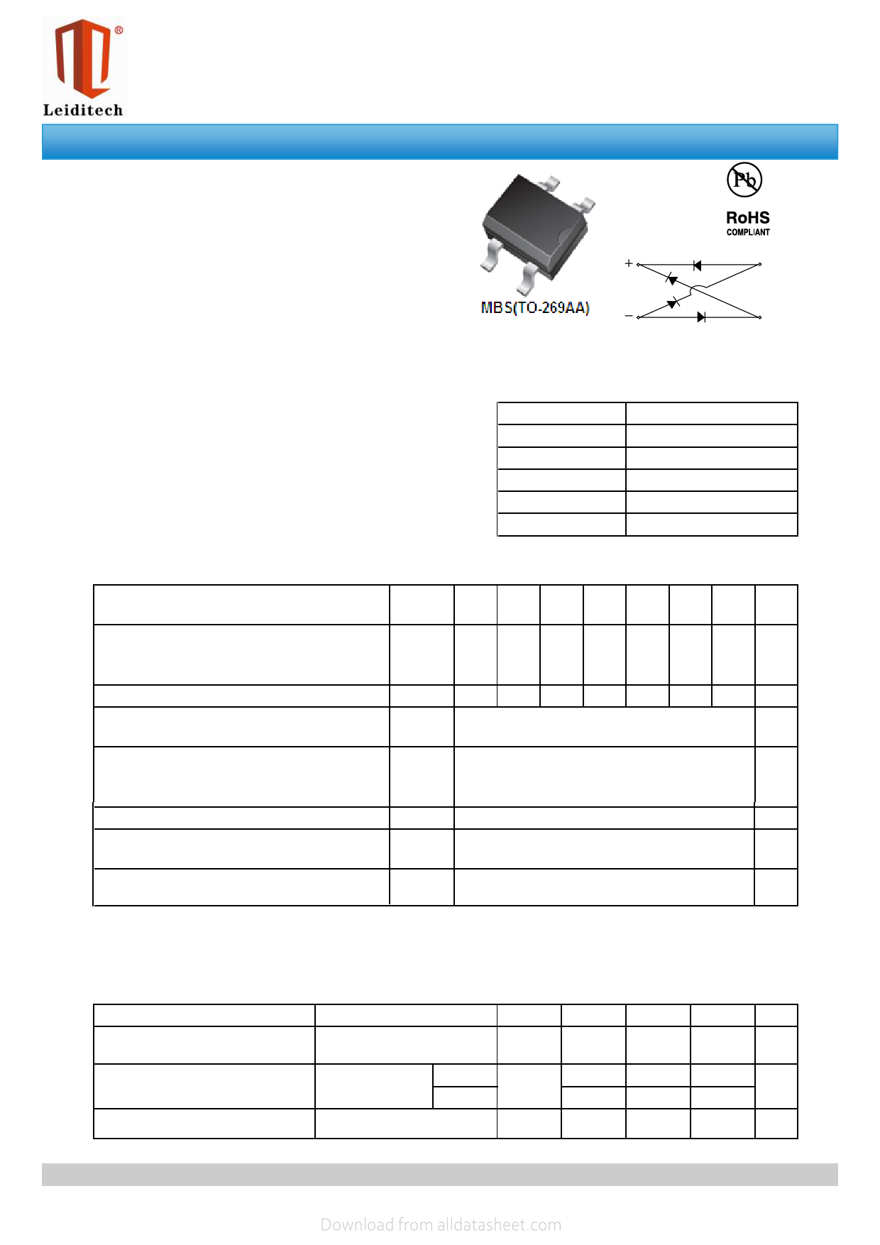
● Case:MBS Molded plastic over glass passivated chip
● Terminals: Solder plated,solderable per
J-STD-002B and JESD22-B102D
● Polarity: Polarity symbols marked on body
MB05S~MB10S
Surface Mount Bridge Rectifiers
~
~
Major Ratings and Characteristics
IF?(AV)
0.5A
VRRM
50 V to 1000 V
IFSM
35 A
IR
5 μA
VF
1.0V
Tj max.
150 °C
Maximum Ratings & Thermal Characteristics (TA = 25 °C unless otherwise noted)
Items
Symbol
MB
05S
MB
1S
MB
2S
MB
4S
MB
6S
Peak Repetitive Reverse Voltage
Working Peak Reverse Voltage
DC Blocking Voltage
RMS Reverse Voltage
Maximum average forward output rectified
current (see Fig.1)
VRRM
VRWM
VR
50 100 200 400 600
VR(RMS) 35 70 140 280 420
IF(AV)
0.5 (1)/0.8 (2)
MB
8S
MB
10S
UNIT
800 1000 V
560 700 V
A
Peak Forward Surge Current 8.3ms Single half
sine-wave superimposed on rated load(JEDEC
IFSM
Method)
35
A
Thermal resistance from junction to lead
RθJL
Thermal resistance from junction to ambient
RθJA
20(1)
85 (1)
(2)
70
℃/ W
℃/ W
Operating junction and storage temperature
range
TJ, TSTG
–55 to +150
℃
Notes: (1)On glass epoxy P.C.B. mounted on 0.05 x 0.05" (1.3 x 1.3 mm) pads
(2)On aluminum substrate P.C.B. with an area of 0.8" x 0.8" (20 x 20 mm) mounted on 0.05 x 0.05" (1.3 x 1.3 mm) solder pad
Electrical Characteristics (TA = 25 °C unless otherwise noted)
Items
Maximum instantaneous forwad
voltage drop per leg
Reverse current
Typical junction capacitance
Test conditions
Symbol Min
IF=0.4A
VF
-
VR=VDC
TA=25℃
TA=125℃
IR
-
-
4.0 V ,1MHz
CJ
-
Type
-
-
-
13
Max UNIT
1.0
V
5
μA
100
-
pF
Rev : 01.06.2014
1/3
www.leiditech.com
Share Link: 