MAX825YEXK データシートの表示(PDF) - Maxim Integrated
部品番号
コンポーネント説明
メーカー
MAX825YEXK
Maxim Integrated

MAX825YEXK Datasheet PDF : 10 Pages
| |||
5-Pin Microprocessor Supervisory Circuits With
Watchdog Timer and Manual Reset
_______________Detailed Description
RESET Output
A microprocessor’s (µP’s) reset input starts the µP in a
known state. The MAX823/MAX824/MAX825 µP super-
visory circuits assert a reset to prevent code-execution
errors during power-up, power-down, and brownout
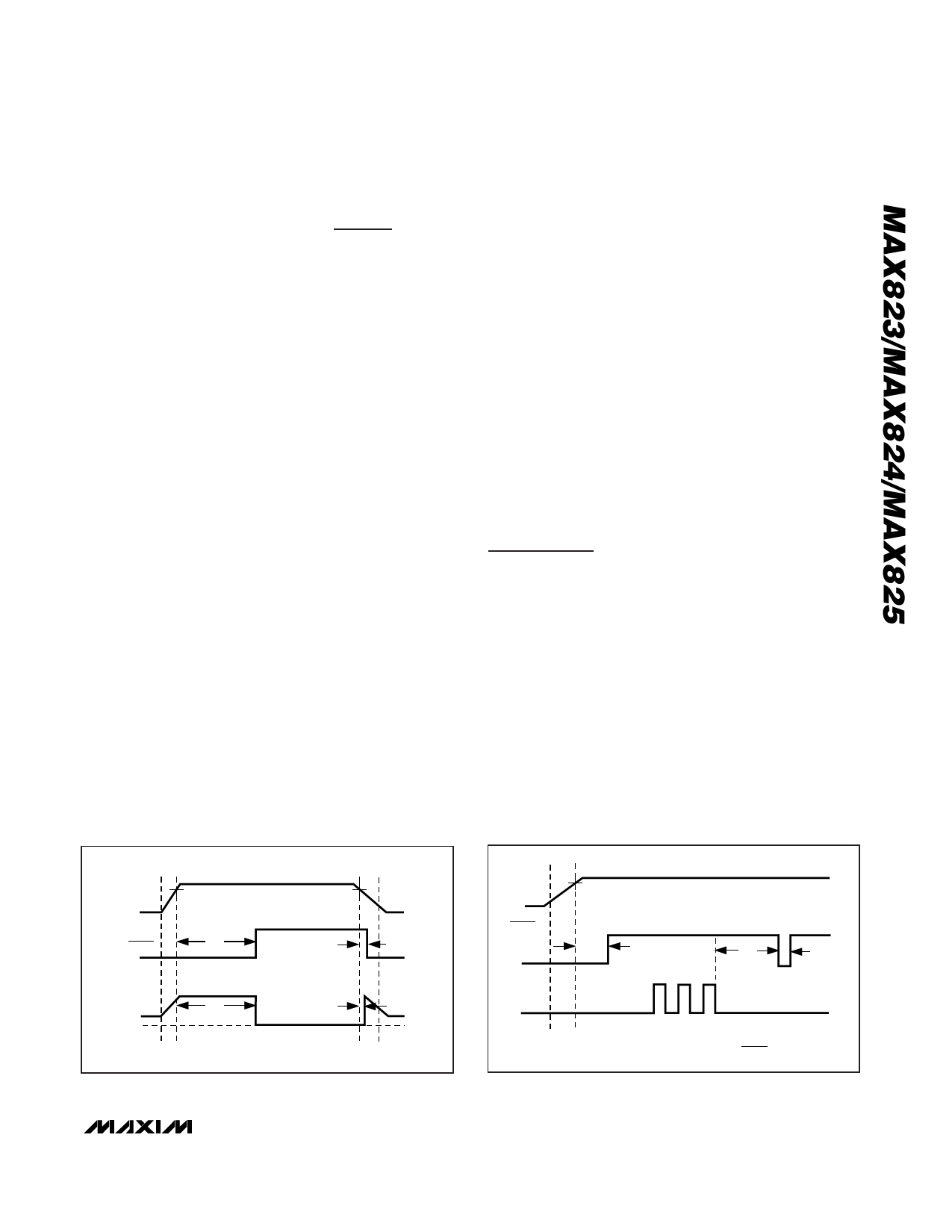
conditions. RESET is guaranteed to be a logic low for
VCC down to 1V. Once VCC exceeds the reset thresh-
old, an internal timer keeps RESET low for the specified
reset timeout period (tRP); after this interval, RESET
returns high (Figure 2).
If a brownout condition occurs (VCC dips below the
reset threshold), RESET goes low. Each time RESET is
asserted it stays low for the reset timeout period. Any
time VCC goes below the reset threshold the internal
timer restarts. RESET both sources and sinks current.
RESET on the MAX824/MAX825 is the inverse of
RESET.
Manual Reset Input (MAX823/MAX825)
Many µP-based products require manual reset capabili-
ty, allowing the operator, a test technician, or external
logic circuitry to initiate a reset. On the MAX823/
MAX825, a logic low on MR asserts reset. Reset remains
asserted while MR is low, and for tRP (200ms nominal)
after it returns high. MR has an internal 52kΩ pullup
resistor, so it can be left open if not used. This input can
be driven with CMOS logic levels or with open-drain/
collector outputs. Connect a normally open momentary
switch from MR to GND to create a manual-reset func-
tion; external debounce circuitry is not required. If MR is
driven from long cables or the device is used in a noisy
environment, connect a 0.1µF capacitor from MR to
GND to provide additional noise immunity.
Watchdog Input (MAX823/MAX824)
In the MAX823/MAX824, the watchdog circuit monitors
the µP’s activity. If the µP does not toggle the watchdog
input (WDI) within tWD (1.6s), reset asserts. The internal
1.6s timer is cleared by either a reset pulse or by tog-
gling WDI, which detects pulses as short as 50ns.
While reset is asserted, the timer remains cleared and
does not count. As soon as reset is released, the timer
starts counting (Figure 3).
Disable the watchdog function by leaving WDI uncon-
nected or by three-stating the driver connected to WDI.
The watchdog input is internally driven low during the
first 7/8 of the watchdog timeout period and high for the
last 1/8 of the watchdog timeout period. When WDI is
left unconnected, this internal driver clears the 1.6s
timer every 1.4s. When WDI is three-stated or uncon-
nected, the maximum allowable leakage current is
10µA and the maximum allowable load capacitance is
200pF.
Applications Information
Watchdog Input Current
The MAX823/MAX824 WDI inputs are internally driven
through a buffer and series resistor from the watchdog
counter (Figure 1). When WDI is left unconnected, the
watchdog timer is serviced within the watchdog timeout
period by a low-high-low pulse from the counter chain.
For minimum watchdog input current (minimum overall
power consumption), leave WDI low for the majority of
the watchdog timeout period, pulsing it low-high-low
once within the first 7/8 of the watchdog timeout period
to reset the watchdog timer. If WDI is externally driven
high for the majority of the timeout period, up to 160µA
can flow into WDI.
VCC
1V
RESET
VRST
tRP
VRST
1V
tRD
VCC
tRST
RESET*
tRP
tWD
tRP
RESET
tRP
GND
tRD
WDI
*RESET ON THE MAX824/MAX825 IS THE INVERSE OF RESET.
Figure 2. Reset Timing Diagram
Figure 3. MAX823/MAX824 Watchdog Timing Relationship
_______________________________________________________________________________________ 7
Share Link: