HT9480(1998) データシートの表示(PDF) - Holtek Semiconductor
部品番号
コンポーネント説明
メーカー
HT9480 Datasheet PDF : 57 Pages
| |||
HT9480
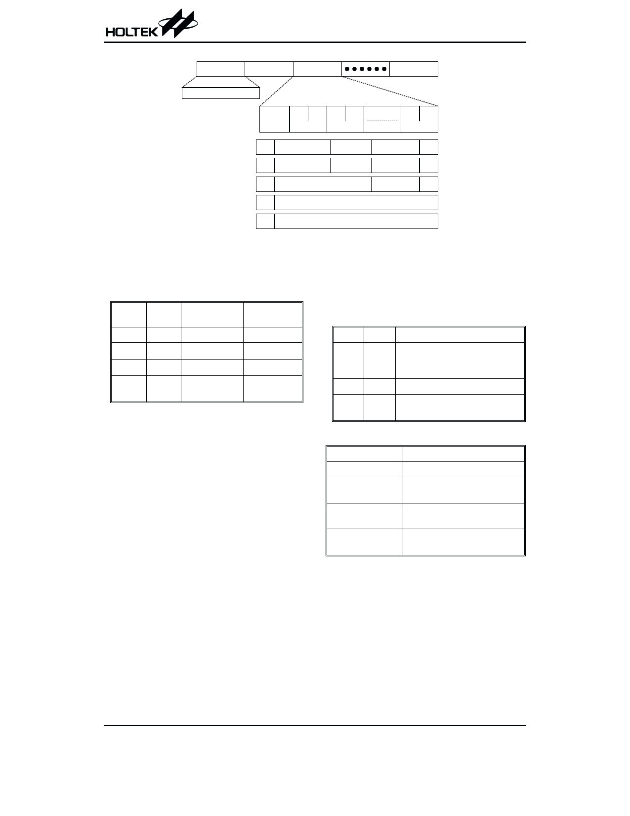
The states of the registers are summarized below.
Register
Power-on
reset (POR)
WDT time-out
(normal
operation)
RES reset
(normal
operation)
TMR0
xxxx xxxx
uuuu uuuu
uuuu uuuu
TMRC0
00-0 1---
00-0 1---
00-0 1---
TMR1
xxxx xxxx
uuuu uuuu
uuuu uuuu
TMRC1
00-0 1---
00-0 1---
00-0 1---
PC
0000H
0000H
0000H
MP0
xxxx xxxx
uuuu uuuu
uuuu uuuu
MP1
xxxx xxxx
uuuu uuuu
uuuu uuuu
ACC
xxxx xxxx
uuuu uuuu
uuuu uuuu
TBLP
xxxx xxxx
uuuu uuuu
uuuu uuuu
TBLH
xxxx xxxx
uuuu uuuu
uuuu uuuu
STATUS --00 xxxx
--1u uuuu
--uu uuuu
INTC
-000 0000
-000 0000
-000 0000
WDTS
0000 0111
0000 0111
0000 0111
PA
1111 1111
1111 1111
1111 1111
PAC
1111 1111
1111 1111
1111 1111
PB
1111 1111
1111 1111
1111 1111
PBC
1111 1111
1111 1111
1111 1111
PC
---- 1111
---- 1111
---- 1111
PCC
---- 1111
---- 1111
---- 1111
RES reset
(HALT)
uuuu uuuu
00-0 1---
uuuu uuuu
00-0 1---
0000H
uuuu uuuu
uuuu uuuu
uuuu uuuu
uuuu uuuu
uuuu uuuu
--01 uuuu
-000 0000
0000 0111
1111 1111
1111 1111
1111 1111
1111 1111
---- 1111
---- 1111
WDT time-
out (HALT)*
uuuu uuuu
uu-u u--
uuuu uuuu
uu-u u--
0000H
uuuu uuuu
uuuu uuuu
uuuu uuuu
uuuu uuuu
uuuu uuuu
--11 uuuu
-uuu uuuu
uuuu uuuu
uuuu uuuu
uuuu uuuu
uuuu uuuu
uuuu uuuu
---- uuuu
---- uuuu
Note: “*” means “warm reset”
“u” means “unchanged”
“x” means “unknown”
The measured result will remain in the
timer/event counter even when the activated
transient occurs again. In other words, only one
cycle measurement can be made until the TON
is set. The cycle measurement will re-function
as long as further transient pulses are received.
Note that, in this operation mode, the
timer/event counter starts counting not accord-
ing to the logic level but to the transient edges.
In the case of counting overflows, the counter is
re-loaded from its counter preload register and
issues an interrupt request, similar to the other
two modes.
To enable the counting operation, the value of
the timer on bit (TON; bit 4 of TMRC0 and
TMRC1) is “1”. In the pulse width measurement
mode, the TON is automatically cleared after
the measurement cycle is completed. In the
other two modes, namely the event count or
timer mode, the TON can be reset only by in-
structions. The overflow of the programmable
timer counter and of the timer/event counter
can be configured as one of the wake-up
sources. No matter what type of operation mode
is chosen, writing a 0 to ET0I and ET1I disables
the interrupt service of the programmable
timer counter and the timer/event counter, re-
spectively.
19
23th Feb ’98
Share Link: 