CS61574A データシートの表示(PDF) - Cirrus Logic
部品番号
コンポーネント説明
メーカー
CS61574A Datasheet PDF : 34 Pages
| |||
-XO 
&21),'(17,$/
CS61574A CS61575
-/$%
&5.#4)/.
%84%.$%$
0). (!2$7!2% (!2$7!2%
42!.3-)44%2
40/3
4.%'
4$!4!
4#/$%
2.%'
"06
2%#%)6%2$0-
20/3
$0-
2$!4!
!)3
-4)0
2#/$%
-2).'
0#3
,%.
,%.
#/.42/,
,%.
,%.
,%.
,%.
2,//0
2,//0
,,//0
,,//0
4!/3
4!/3
(/34
40/3
4.%'
2.%'
20/3
$0-
-4)0
-2).'
).4
3$)
3$/
#3
3#,+
#,+%
Table 2. Pin Definitions
Transmitter
The transmitter takes digital T1 or E1 input data
and drives appropriately shaped bipolar pulses
onto a transmission line. The transmit data (TPOS
& TNEG or TDATA) is supplied synchronously
and sampled on the falling edge of the input
clock, TCLK.
Either T1 (DSX-1 or Network Interface) or E1
CCITT G.703 pulse shapes may be selected.
Pulse shaping and signal level are controlled by
"line length select" inputs as shown in Table 3.
LEN2 LEN1 LEN0 Option Selected Application
�&%%4
�&%%4
�&%%4
�&%%4
�&%%4
$38
!"!-
!44�"
OR�#
Ω�
Ω�
%
##)44�'
!44�#"
2EPEATER
&##�0!24�
�/04�! .ETWORK
!.3)� 4
)NTERFACE
Table 3. Line Length Selection
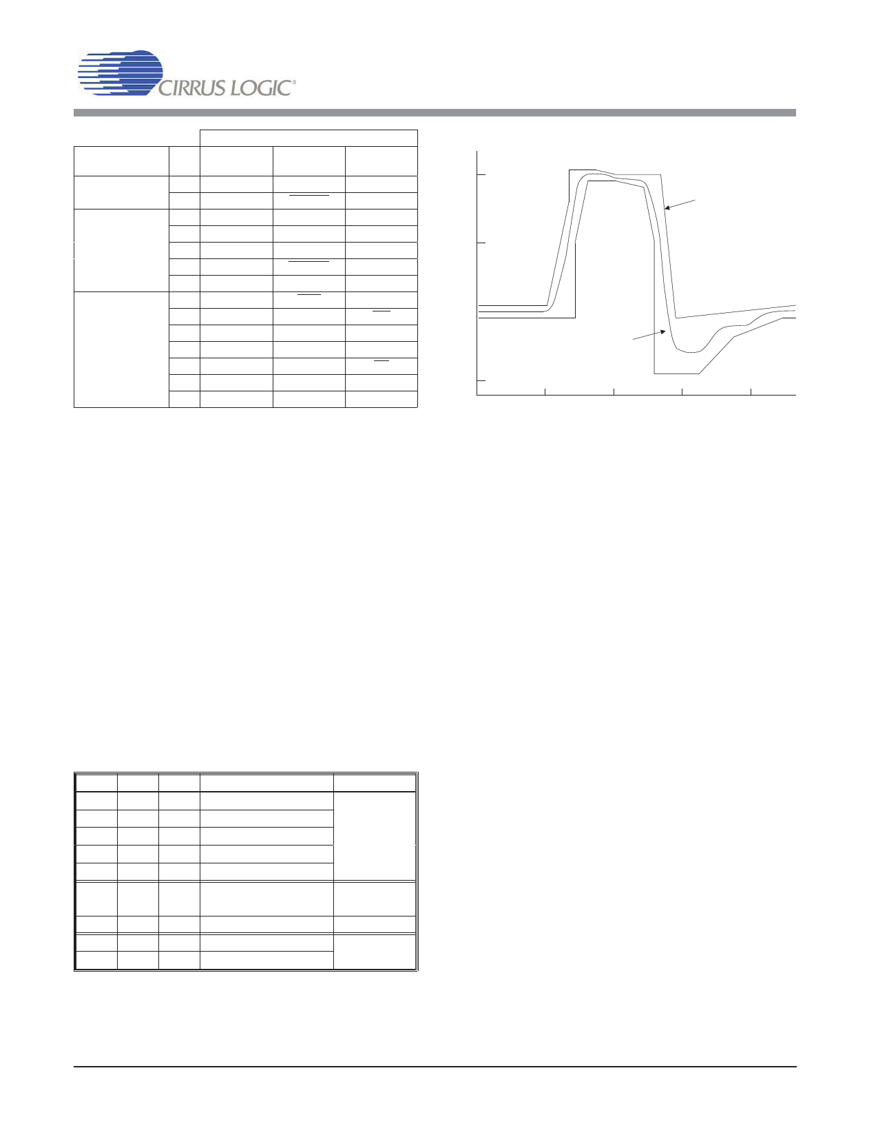
./2-!,):%$
!-0,)45$%
!.3)�4)
!44�#"�
30%#)&)#!4)/.3
/54054
05,3%�3(!0%
4)-%��NANOSECONDS
Figure 8. Typical Pulse Shape at DSX-1 Cross Connect
The CS61575 and CS61574A line drivers are de-
signed to drive a 75 Ω equivalent load.
For E1 applications, the CS61574A and CS61575
drivers provide 14 dB of return loss during the
transmission of both marks and spaces. This im-
proves signal quality by minimizing reflections
off the transmitter. Similar levels of return loss
are provided for T1 applications.
For T1 DSX-1 applications, line lengths from 0 to
655 feet (as measured from the transmitter to the
DSX-1 cross connect) may be selected. The five
partition arrangement in Table 3 meets ANSI
T1.102 and AT&T CB-119 requirements when
using #22 ABAM cable. A typical output pulse is
shown in Figure 8. These pulse settings can also
be used to meet CCITT pulse shape requirements
for 1.544 MHz operation.
For T1 Network Interface applications, two addi-
tional options are provided. Note that the optimal
pulse width for Part 68 (324 ns) is narrower than
the optimal pulse width for DSX-1 (350 ns). The
CS61575 and CS61574A automatically adjusts
the pulse width based upon the "line length" se-
lection made.
DS154F3
11
Share Link: 