FS6377-01G データシートの表示(PDF) - AMI Semiconductor
部品番号
コンポーネント説明
メーカー
FS6377-01G Datasheet PDF : 21 Pages
| |||
FS6377-01/FS6377-01g Programmable 3-PLL Clock Generator IC
Data Sheet
3.1.1 Reference Divider
The reference divider is designed for low phase jitter. The
divider accepts the output of the reference oscillator and
provides a divided-down frequency to the PFD. The
reference divider is an 8-bit divider, and can be
3.1.2 Feedback Divider
The feedback divider is based on a dual-modulus pre-
scaler technique. The technique allows the same
granularity as a fully programmable feedback divider,
while still allowing the programmable portion to operate at
low speed. A high-speed pre-divider (also called a
prescaler) is placed between the VCO and the
programmable feedback divider because of the high
speeds at which the VCO can operate. The dual-modulus
technique insures reliable operation at any speed that the
VCO can achieve and reduces the overall power
consumption of the divider.
For example, a fixed divide-by-eight could be used in the
feedback divider. Unfortunately, a divide-by-eight would
limit the effective modulus of the entire feedback divider to
multiples of eight. This limitation would restrict the ability of
the PLL to achieve a desired input-frequency-to-output-
frequency ratio without making both the reference and
feedback divider values comparatively large.
A large feedback modulus means that the divided VCO
frequency is relatively low, requiring a wide loop band-
width to permit the low frequencies. A narrow loop band-
width tuned to high frequencies is essential to minimizing
jitter; therefore, divider moduli should always be as small
as possible.
programmed for any modulus from 1 to 255 by
programming the equivalent binary value. A divide-by-256
can also be achieved by programming the eight bits to
00h.
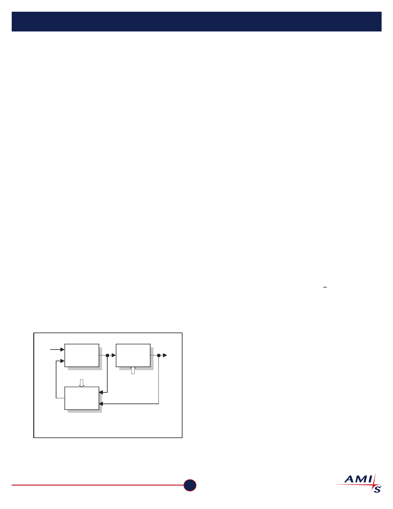
To understand the operation, refer to Figure 4. The M-
counter (with a modulus always equal to M) is cascaded
with the dual-modulus prescaler. The A-counter controls
the modulus of the prescaler. If the value programmed into
the A-counter is A, the prescaler will be set to divide by
N+1 for A prescaler outputs. Thereafter, the prescaler
divides by N until the M-counter output resets the A-
counter, and the cycle begins again. Note that N=8 and A
and M are binary numbers.
Suppose that the A-counter is programmed to zero. The
modulus of the prescaler will always be fixed at N; and the
entire modulus of the feedback divider becomes MxN.
Next, suppose that the A-counter is programmed to a one.
This causes the prescaler to switch to a divide-by-N+1 for
its first divide cycle and then revert to a divide-by-N. In
effect, the A-counter absorbs (or "swallows") one extra
clock during the entire cycle of the feedback divider. The
overall modulus is now seen to be equal to MxN+1.
This example can be extended to show that the feedback
divider modulus is equal to MxN+A, where A<M.
fVCO
Dual
Modulus
Prescaler
FBKDIV[2:0]
A
Counter
M
Counter
fPD
FBKDIV[10:3]
Figure 4: Feedback Divider
AMI Semiconductor
www.amis.com
3
Share Link: 