AD9898 データシートの表示(PDF) - Analog Devices
部品番号
コンポーネント説明
メーカー
AD9898 Datasheet PDF : 52 Pages
| |||
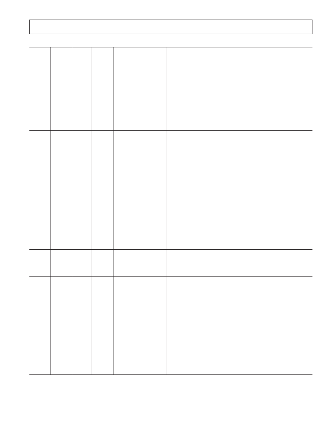
AD9898
Table I. Control Register Address Map (Register Names Are Subject to Change)
Bit Default Register
Address Content Width Value Name
Register Description
0A
23
1
22
1
(21:16) 6
(15:12) 4
(VD
(11:10) 2
SyncReg)* 9
1
8
1
(7:4)
4
(3:2)
2
1
1
0
1
0
0
0x00
0
0
0
0
C
3
0
0
FDPOL
VSGMASK
SYNCCNT
SVREP_MODE
HBLKEXT
HPULSECNT
SPATLOGIC
SVOS
SPAT_EN
MODE
Unused
FD Polarity Control (0 = Low, 1 = High)
VSG Masking (See Table XXIII)
External SYNC Setting
Super Vertical Repetition Mode
H Pulse Blanking Extend Control
H Pulse Control during Blanking
SPAT Logic Setting (See Table XX)
Second V Output Setting (10 = Output Repetition 1)
SPAT Control (0 = SPAT Disable, 1 = SPAT Enable)
Mode Control Bit (0 = Mode_A, 1 = Mode_B)
0B
(23:22) 2
21
1
20
1
(VD
(19:17) 3
SyncReg)* 16
1
15
1
(14:12) 3
11
1
(10:0) 11
0
1
1
0
0
0
0
0
0x7FF
SUBCK_EN
VSG_EN
STROBE_EN
SUBCKNUM_HP
SUBCKNUM
Unused
SUBCK Output Enable Control (0 = Disable, 1 = Enable)
VSG Output Enable Control (0 = Disable, 1 = Enable)
Unused
STROBE Output Control (0 = STROBE Output Held Low,
1 = STROBE Output Enabled)
Unused
High Precision Shutter SUBCLK Pulse Position/Number
Unused
Total Number of SUBCKs per Field
0C
(23:21) 3
20
1
(19:18) 2
(VD
17
1
SyncReg)* 16
1
15
1
(14:12) 3
11
1
(10:0) 11
0
0
0
0
0
0
0
0
0x000
MSHUTINIT
MSHUTEN
MSHUTPOS_HP
MSHUTPOS
Unused
MSHUT Initialize (1 = Forces MSHUT Low)
Unused
Unused
MSHUT Control ( 0 = MSHUT Held at Last State, 1 = MSHUT Output)
Unused
MSHUT Position during High Precision Operation
Unused
MSHUT Position during Normal Operation
0D
(23:17) 7
16
1
(VD
(15:11) 5
SyncReg)* (10:0) 11
0
0x000
VSUBPOL
VSUBTOG
Unused
VSUB Active Polarity (0 = Low, 1 = High)
Unused
VSUB Toggle Position. Active starting line in any field.
0E
(23:21) 3
20
1
(19:18) 2
(VD
17
1
SyncReg)* 16
1
(15:10) 6
(9:0)
10
0
0
0
0
0
0x00
0x000
VGAGAIN
Unused
Unused. Test Mode. Should be set = 0.
Unused
Unused. Test Mode. Should be set = 0.
Unused. Test Mode. Should be set = 0.
Unused
VGA Gain
D5
(23:4) 20
0x00000
3
1
1
DCLK2SEL
2
1
0
DCLK1SEL
(1:0)
2
0
CLKDIV
Unused
DCLK2 Selector (0 = Select Internal FD Signal to be Output on FD/
DCLK2 Pin 16, 1 = Select CLI to be Output on FD/DCLK2 Pin 16)
DCLK1 Selector (0 = Select DLL Version for DCLK1 Output,
1 = Select CLI for DCLK1 Output)
Input Clock Divider (0 = No Division, 1 = 1/2, 2 = 1/3, 3 = 1/4)
D6
(23:1) 23
0x000000
0
1
1
SLAVE_MODE
Unused
Operating Mode ( 0 = Master Mode, 1 = Slave Mode)
*This register defaults to VD synchronous mode type at power up. VD sync type registers do not get updated until the first falling edge of VD is asserted after the
register has been programmed. VD sync type registers can be programmed to be asynchronous registers by setting VDMODE = 1 (Addr 0x01).
REV. 0
–11–
Share Link: 