AN701 データシートの表示(PDF) - Vishay Semiconductors
部品番号
コンポーネント説明
メーカー
AN701
Vishay Semiconductors

AN701 Datasheet PDF : 19 Pages
| |||
The average input current will be determined by:
Pin 17.65
IDC + Vin + 48 + 0.358 A
Pin
17.65
IA + Vin x d + 48 x 0.376 + 0.98 A
From this equation the RMS value can also be calculated to be
approximately 0.475 A.
The Marcon TCCR70E2A335 3.3-mF, 100-Vdc capacitor has an
ESR rating of 20 mΩ at 500 kHz. This type will therefore dissipate
P = 0.4752 x 0.020 = 4.5 mW due to the switching current. The
ripple produced across this device will be governed by the
discharging current of the capacitor less the input dc voltage
in accordance with:
Q=ixt=CxV
NVripple
+
IC x
C
t
where t +
tsw x d and IC + IA–IDC
0.612 A x 2 ms x 0.376
NVripple +
3.3 mF
+ 0.14 V
140 mV of ripple is probably acceptable as a first stage of
filtering. If lower ripple is required at the input, then a two stage
filter will yield better results.
Output capacitor:
DIout
Cout + 8fDVout whereDIout + 0.1 x Iout
DVout = maximum output ripple voltage
f = operating frequency
0.3 A
Cout + 8 x 500 kHz x 50 mV + 1.5 mF
The required ESR for obtaining 50 mV of ripple would be
defined by:
DVout
ESRmax + DIout
50 mV
ESRmax + 0.3 A + 167 mW
In practice, it is impossible to precisely match the value of a
capacitor with the required ESR, and the values of the
capacitors must often be selected to cover all operating
conditions including voltage and temperature.
The above equations and calculations are meant to help the
designer select the approximate size of the components
required, with the final selection based on practical values that
meet the minimum required. In designs operating below
500 kHz, the choice of the capacitor is dictated by the ESR,
and the best high-frequency electrolytics often require
large-size and micro-farad values to meet these
requirements. When operating at 500 kHz, the choice
becomes more based on the practical value closest to the size
and voltage rating required. For example, with electrolytics, in
Document Number: 70575
16-Jan-01
AN701
Vishay Siliconix
order to guarantee the ESR over temperature or age, it might
have been necessary to use a radial 1000-mF, 6.3-V Aluminum
Electrolytic in a 10x16 mm case (1257 mm2) to get an ESR
value below 100 mW. It would also be necessary to check the
ESR with frequency at 500 kHz, as this data is seldom offered
for electrolytics. By comparison, the Marcon TCCR70E1E106
10-mF, 25-Vdc is available in 7.5 x 6.3 x 2.75 (130 mm2) and
has an ESR of less than 15 mW at 500 kHz. This will be ideal
for low output ripple an noise. Recently introduced organic
semiconductor electrolytics offer substantial improvements
and could also be considered. In this example, it was decided
to use 2 x 10-mF capacitors in order to obtain low output ripple.
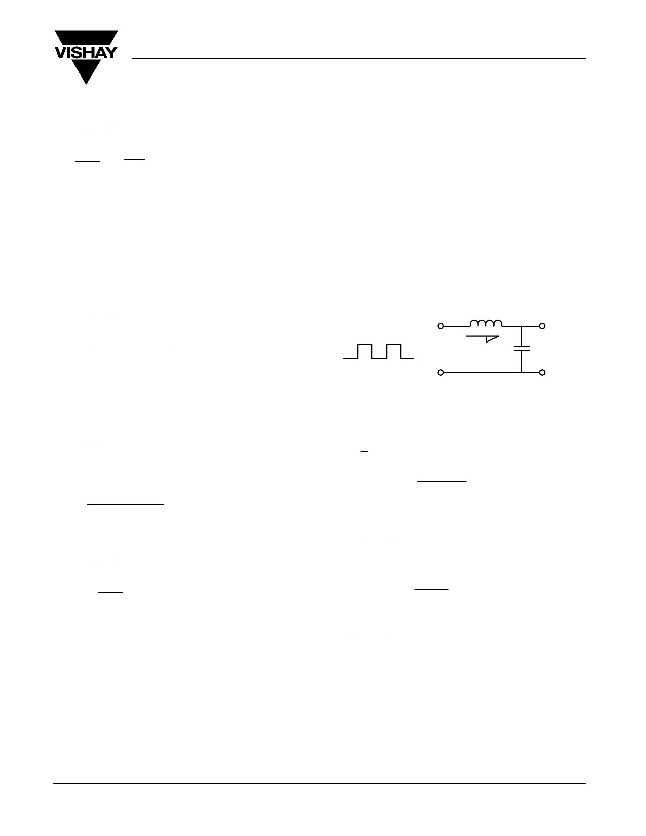
OUTPUT INDUCTOR DESIGN
The output inductor limits the rate at which the current flows
into the output capacitor when the voltage is applied from the
primary through the transformer (Figure 21).
Lout
Ein
iL
Cout
Eout
Figure 21
From simple circuit theory, the voltage applied across an
inductor is:
di
VL + L dt
where
VL + Ein–Eout
and
di
+
DIL
then
L
+
ǒEin–EoutǓxDt
DIL
In forward converters, at maximum duty cycle,
Ein = 2xEout, and:
1
toff + 2 x FSW
In this case, substituting gives:
Eout x toff
toff + 1mS and L + DIL
Therefore
5 V x 1 mS
L + 0.3 A + 16.7 mH
In practice, an inductor between 5 and 10 mH would be an
acceptable choice, allowing for manufacturing tolerances and
variations.
The core selected is the EF12.6, which is identical to the core
selected for the transformer design. The EF12.6 is a cheap,
low-profile design available from many suppliers in all parts of
the world. A surface-mounted version of this bobbin was
selected for a design that could be entirely machine wound and
terminated. This implies that larger wire sizes are not possible,
due to automated winding restrictions.
www.vishay.com
11
Share Link: