ATF-541M4 データシートの表示(PDF) - HP => Agilent Technologies
部品番号
コンポーネント説明
メーカー
ATF-541M4
HP => Agilent Technologies

ATF-541M4 Datasheet PDF : 16 Pages
| |||
ATF-541M4 Typical Scattering Parameters, VDS = 4V, IDS = 60 mA
Freq.
GHz
S11
Mag. Ang.
S21
dB
Mag. Ang.
S12
Mag. Ang.
0.1
0.99
-17.5
0.5
0.87
-74.8
0.9
0.78
-110.7
1.0
0.76
-117.5
1.5
0.72
-141.4
1.9
0.70
-154.3
2.0
0.69
-159.0
2.5
0.69
-170.1
3.0
0.69
-179.6
4.0
0.69
165.9
5.0
0.70
153.9
6.0
0.70
138.8
7.0
0.72
128.6
8.0
0.73
118.8
9.0
0.75
109.5
10.0
0.76
99.9
11.0
0.77
90.1
12.0
0.79
81.5
13.0
0.81
71.6
14.0
0.83
62.2
15.0
0.85
51.9
16.0
0.87
42.1
17.0
0.90
32.7
18.0
0.90
24.2
28.39
26.07
23.18
22.47
19.60
17.79
17.25
15.50
13.98
11.60
9.72
8.31
6.96
5.82
4.80
3.89
3.07
2.27
1.47
0.68
-0.28
-1.39
-2.28
-3.52
26.27
20.12
14.42
13.29
9.55
7.75
7.29
5.96
5.00
3.80
3.06
2.60
2.23
1.95
1.74
1.56
1.42
1.30
1.19
1.08
0.97
0.85
0.77
0.67
168.9
133.9
113.6
109.4
95.1
86.9
85.6
77.7
70.6
57.9
46.4
34.4
23.9
13.5
3.6
-6.6
-17.1
-27.6
-37.8
-48.9
-59.6
-69.7
-78.7
-87.4
0.01
81.0
0.03
54.5
0.04
41.6
0.04
39.4
0.04
35.2
0.05
33.3
0.05
33.7
0.051
34.2
0.05
33.1
0.06
33.2
0.07
32.4
0.08
29.5
0.09
26.4
0.10
22.7
0.11
18.2
0.13
13.4
0.14
7.2
0.15
0.6
0.16
-6.5
0.17
-13.9
0.17
-21.7
0.17
-29.9
0.18
-37.8
0.17
-44.8
S22
Mag. Ang.
0.56
-10.7
0.44
-44.7
0.32
-64.3
0.29
-68.3
0.21
-82.7
0.18
-91.2
0.14
-93.8
0.11
-103.7
0.10
-117.7
0.09
-141.7
0.09
-166.9
0.10
-175.8
0.12
163.3
0.13
149.1
0.14
138.2
0.17
126.7
0.20
114.9
0.24
103.7
0.29
93.3
0.35
84.3
0.42
75.0
0.48
67.0
0.55
61.1
0.61
56.4
MSG/MAG
dB
34.19
28.27
25.57
25.21
23.78
21.90
21.64
20.68
17.98
15.13
13.17
11.68
10.53
9.44
8.76
8.01
7.30
6.91
6.54
6.22
5.73
5.20
6.31
5.96
Typical Noise Parameters, VDS = 4 V, IDS = 60 mA
Freq
Fmin
GHz
dB
Γopt
Mag.
Γopt
Ang.
Rn/50
0.5
0.13
0.36
14.2
0.05
0.9
0.16
0.35
13.3
0.06
1.0
0.20
0.22
33.7
0.05
1.9
0.45
0.22
101.6
0.05
2.0
0.47
0.20
102.7
0.06
2.4
0.57
0.24
126.0
0.05
3.0
0.63
0.29
148.9
0.05
3.9
0.73
0.35
172.3
0.04
5.0
1.05
0.37
-168.4
0.05
5.8
1.21
0.38
-155.9
0.06
6.0
1.23
0.41
-151.0
0.08
7.0
1.43
0.45
-139.9
0.11
8.0
1.61
0.51
-129.9
0.15
9.0
1.80
0.57
-114.8
0.26
10.0
2.01
0.61
-99.2
0.41
Ga
dB
27.18
22.95
22.51
19.14
18.66
17.61
16.26
14.58
13.04
12.01
11.05
10.11
9.76
8.95
8.44
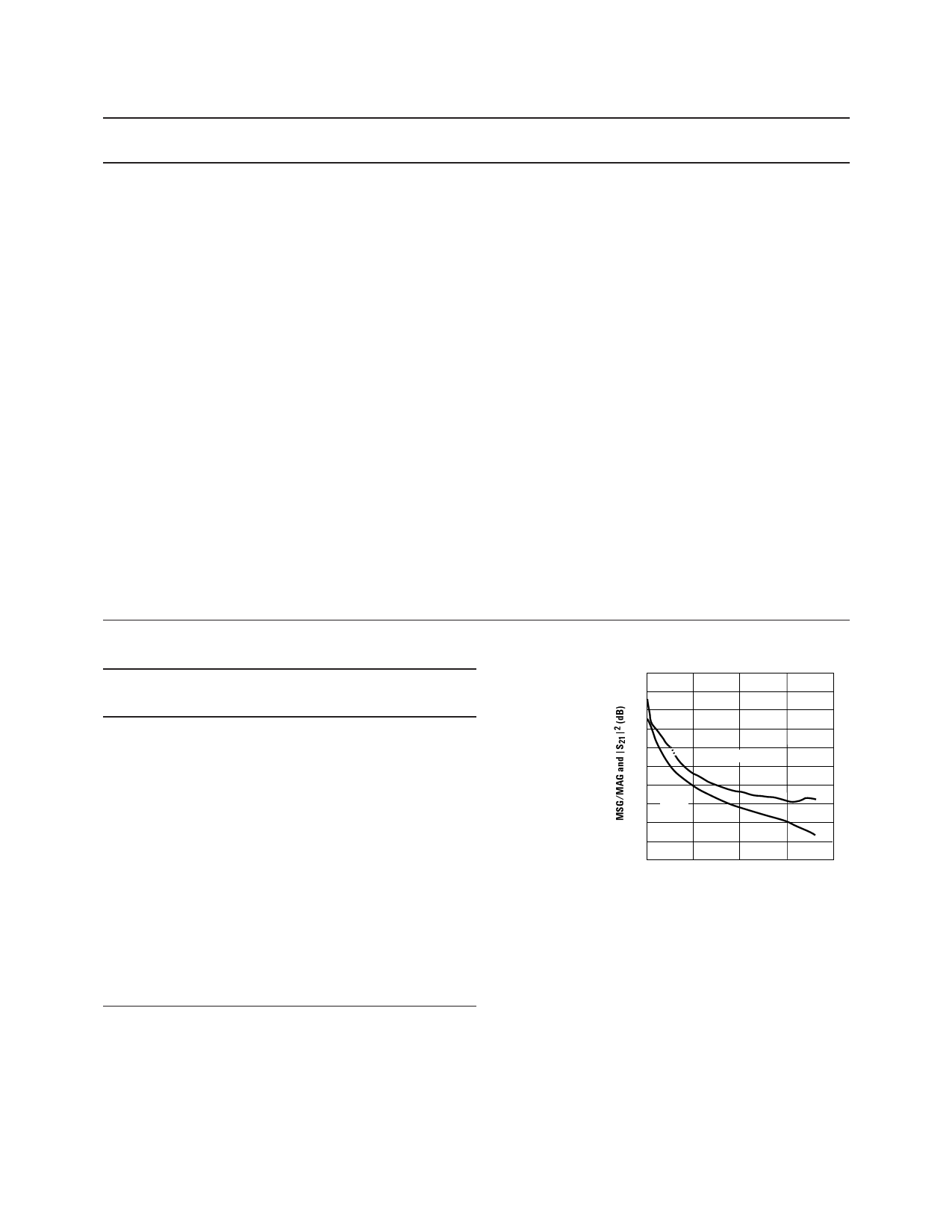
40
35
MSG
30
25
20
MAG
15
10
5
|S21|2
0
-5
-10
0
5
10
15
20
FREQUENCY (GHz)
Figure 19. MSG/MAG and |S21|2 vs.
Frequency at 4V, 60 mA.
Notes:
1. The Fmin values are based on a set of 16 noise figure measurements made at 16 different impedances using an ATN NP5 test system. From these
measurements a true Fmin is calculated. Refer to the noise parameter application section for more information.
2. Refer to the applications section for additional information on the test fixture used for the measurement of the s and noise parameters.
9
Share Link: