CS61581-IL(2005) データシートの表示(PDF) - Cirrus Logic
部品番号
コンポーネント説明
メーカー
CS61581-IL Datasheet PDF : 37 Pages
| |||
CS61581
Long Haul
LB02
0
0
1
1
LB01
0
1
0
1
Output Pulse
0 dB
-7.5 dB
-15 dB
-22.5 dB
Short Haul
Transformer Turns
Ratio
Mode
Transmit Receive
HDW or MATCHZ* = 0 1:2
1:1
MATCHZ* = 1
1:1.5
1:1
* MATCHZ = CR2.5
LEN2
0
0
0
1
1
1
1
0
0
LEN1
0
0
1
0
0
1
1
1
1
LEN0
0
1
1
0
1
0
1
1
0
Output Pulse
E1
2.37 V
E1
3.0 V
DSX-1
0’-133’
DSX-1
133’-266’
DSX-1
266’-399’
DSX-1
399’-533’
DSX-1
533’-655’
ANSI
T1.403
FCC Part 68,
Option A
6.0 V
Line Z
75.
120.
100.
100.
100.
100.
100.
100.
100.
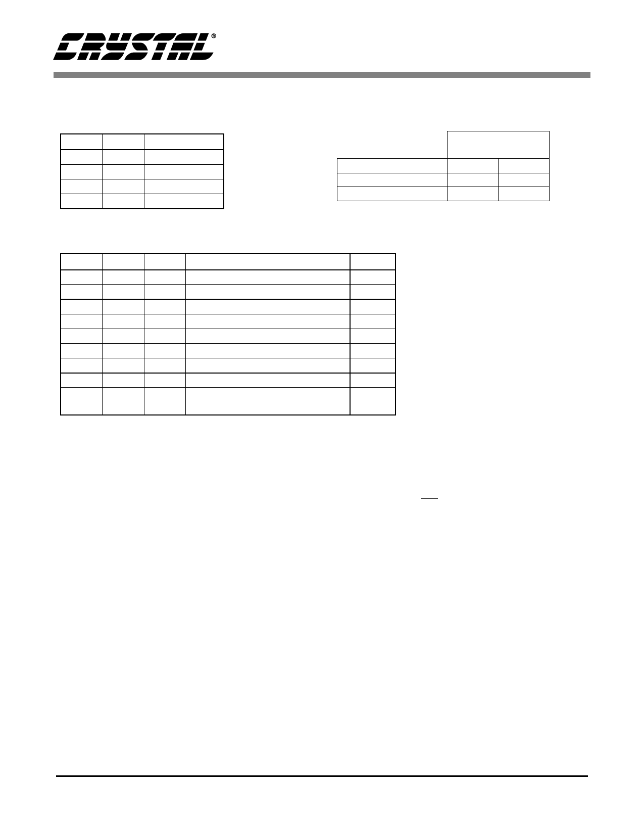
Table 1. Pulse Shape Selection and Transformer Requirements
loading from external components such as high
voltage protection devices.
For T1 DSX-1 applications, line lengths from 0 to
655 feet (as measured from the transmitter to the
DSX-1 cross connect) may be selected. The five
partition arrangement in Table 1 meets ANSI
T1.102 pulse shape requirements when using #22
ABAM or AT&T 600 series cable. A typical output
pulse is shown in Figure 6. These pulse settings can
also be used to meet ITU-T pulse shape require-
ments for 1.544 MHz operation. Short haul pulse
shapes for T1 and E1 are selected by the LEN[2:0]
bits in Control Register 1.
Note that when the device is operated at E1 fre-
quency in the hardware mode, it defaults to low im-
pedance, long haul mode. The pulses driven by the
transmitter in this mode are T1.403 (350ns) pulses
with an overshoot and an undershoot. To drive
pulses without overshoot and undershoot in E1
long haul mode, the E1_LH bit (CR3.6) must be set
to 1, with the SH/LH bit (CR2.0) set to 0.
The E1 G.703 pulse shape is supported with line
length selections LEN[2:0] = 000 for 2.37 V 75.
applications or LEN[2:0] = 001 for 3.0 V 120 . ap-
plications. The output pulse will meet the G.703
pulse shape template shown in Figure 7. The output
impedance of the driver will adjust according to the
pulse shape selected.
In the short haul mode, setting the LEN[2:0] bits
also controls the transmitter output impedance. For
long haul operation, driver impedance is deter-
mined by the desired selection of MATCHZ and
E1_LH bits. When MATCHZ is set to “0” the out-
put impedance is low, and the impedance presented
to the line is controlled by external resistors. When
MATCHZ is set to 1, E1_LH determines whether
DS211PF1P8
11
Share Link: 