EL4089 データシートの表示(PDF) - Intersil
部品番号
コンポーネント説明
メーカー
EL4089 Datasheet PDF : 9 Pages
| |||
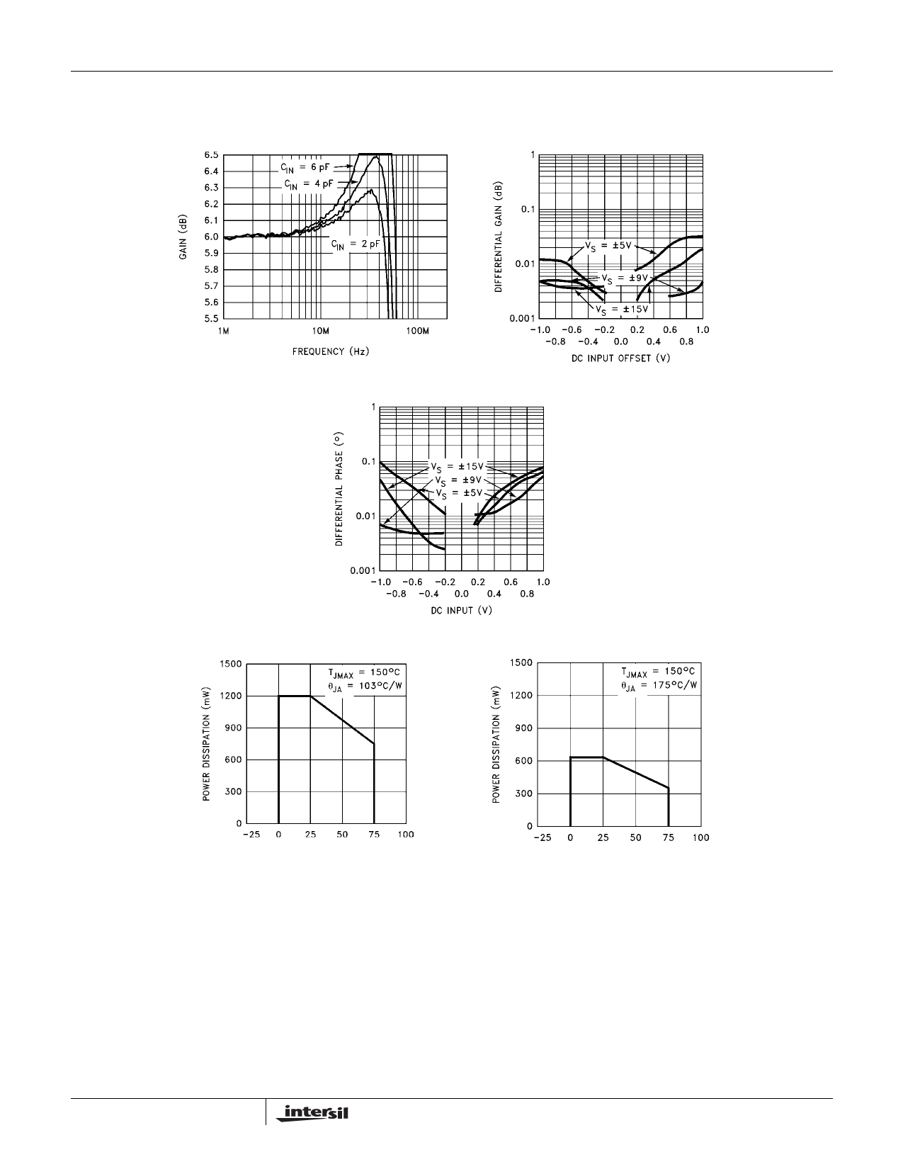
Typical Performance Curves (Continued)
Frequency Response Flatness
vs CIN-; AV = 2; RF = 300Ω
EL4089
Differential Gain vs DC Input
Offset; AV = 2, FO = 3.58MHz,
RL = 150Ω
Differential Phase vs DC Input
Offset; AV = 2; FO = 3.58MHz;
RL = 150Ω
8-Pin Plastic DIP
Maximum Power Dissipation
vs Ambient Temperature
8-Lead SO
Maximum Power Dissipation
vs Ambient Temperature
Typical Application
The EL4089 can be used to DC-restore a video waveform
(see Figure 1). The circuit forces the cable driving video
amplifier’s output to ground when the HOLD pin is at a logic
low.
The “correction voltage” is stored on capacitor CX1, an
external ceramic capacitor. The capacitor value is chosen
from the system requirements. The typical input bias current
to the video amplifier is 1µA, so for a 62µs hold time, and a
6
0.01µF capacitor, the output voltage drift is 6.2mV in one
line.
The S/H amplifier can provide a typical current of 300µA to
charge capacitor CX1, so with a 1.2µs sampling time, the
output can be corrected by 36mV in each line.
Using a smaller value of CX1 increases both the voltage that
can be corrected, and the drift while being held, likewise,
using a larger value of CX1, reduces the voltages.
The RX1 resistor is in the circuit purely to simulate some
external source impedance, and is not needed as a real
Share Link: 