FAN5026 データシートの表示(PDF) - Fairchild Semiconductor
部品番号
コンポーネント説明
メーカー
FAN5026 Datasheet PDF : 17 Pages
| |||
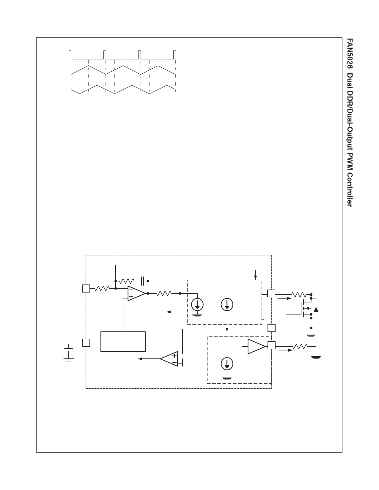
CLK
VDDQ
VTT
Figure 9. Optimal 90° Phasing for DDR2
Initialization and Soft Start
Assuming EN is high, FAN5026 is initialized when VCC
exceeds the rising UVLO threshold. Should VCC drop
below the UVLO threshold, an internal Power-On Reset
function disables the chip.
The voltage at the positive input of the error amplifier is
limited by the voltage at the SS pin which is charged with
a 5µA current source. Once CSS has charged to VREF
(0.9V) the output voltage will be in regulation. The time it
takes SS to reach 0.9V is:
T0.9
=
0----.--9----×-----C-----S---S--
5
(1)
where T0.9 is in seconds if CSS is in µF.
When SS reaches 1.5V, the Power Good outputs are
enabled and hysteretic mode is allowed. The converter is
forced into PWM mode during soft start.
Current Processing Section
The following discussion refers to Figure 10.
The current through RSENSE resistor (ISNS) is sampled
shortly after Q2 is turned on. That current is held, and
summed with the output of the error amplifier. This effec-
tively creates a current mode control loop. The resistor
connected to ISNSx pin (RSENSE) sets the gain in the
current feedback loop. For stable operation, the voltage
induced by the current feedback at the PWM comparator
input should be set to 30% of the ramp amplitude at
maximum load current and line voltage. The following
expression estimates the recommended value of RSENSE
as a function of the maximum load current (ILOAD(MAX))
and the value of the MOSFET’s RDS(ON):
RSENSE = I--L---O---3-A--0--D--%--(-M----•-A---0X---.-)-1--•-2---R-5----D-•--S--V--(--OI--N--N-(--M)---•--A---4X---.)--1---K--- – 100
(2a)
RSENSE must, however, be kept higher than:
RSENSE(MIN) = I--L---O----A----D----(-M---1--A-5--X--0--)-µ--•--A--R-----D---S----(--O----N---) – 100
(2b)
VSEN
CSS SS
300K
0.17pF
1.5M 17pF
4.14K
TO PWM COMP
Reference and
Soft Start
ILIM det.
S/H
V to I
in +
I1A =
ISNS
I1B =
ISNS
9 in –
2.5V
0.9V
I2 =
4 * ILIM
3
ILIM mirror
ISNS RSENSE
LDRV
PGND
ILIM RILIM
Figure 10. Current Limit / Summing Circuits
10
FAN5026 Rev. 1.0.5
www.fairchildsemi.com
Share Link: 