HCPL-0708 データシートの表示(PDF) - HP => Agilent Technologies
部品番号
コンポーネント説明
メーカー
HCPL-0708 Datasheet PDF : 10 Pages
| |||
Pulse-width distortion (PWD) is
the difference between tPHL and
tPLH and often determines the
maximum data rate capability of
a transmission system. PWD can
be expressed in percent by
dividing the PWD (in ns) by the
minimum pulse width (in ns)
being transmitted. Typically,
PWD on the order of 20 - 30% of
the minimum pulse width is
tolerable; the exact figure
depends on the particular
application.
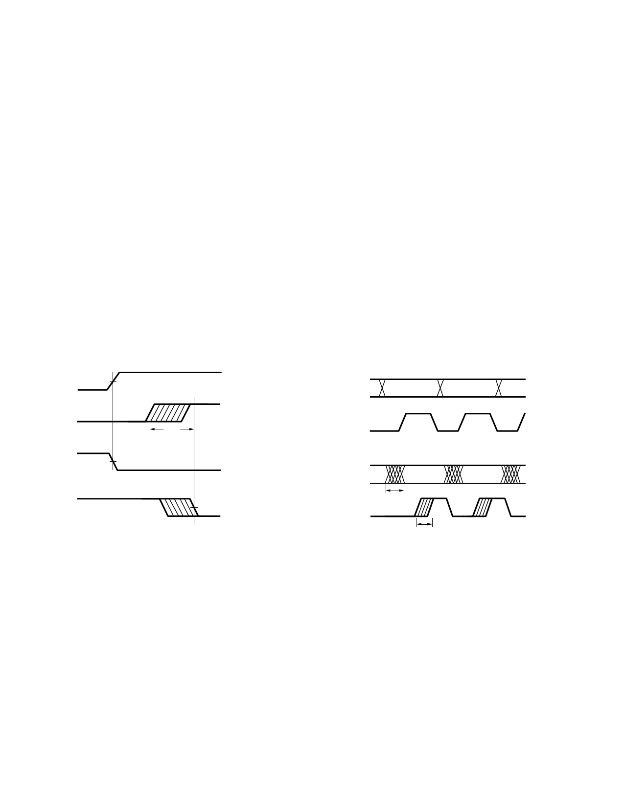
Propagation delay skew, tPSK, is
an important parameter to con-
sider in parallel data applications
where synchronization of signals
on parallel data lines is a
concern. If the parallel data is
being sent through a group of
optocouplers, differences in
propagation delays will cause the
data to arrive at the outputs of
the optocouplers at different
times. If this difference in
propagation delay is large enough
it will determine the maximum
rate at which parallel data can be
sent through the optocouplers.
Propagation delay skew is defined
as the difference between the
minimum and maximum propa-
gation delays, either tPLH or tPHL,
for any given group of optocoup-
lers which are operating under
the same conditions (i.e., the
same drive current, supply volt-
age, output load, and operating
temperature). As illustrated in
Figure 9, if the inputs of a group
of optocouplers are switched
either ON or OFF at the same
time, tPSK is the difference
between the shortest propagation
delay, either tPLH or tPHL, and the
longest propagation delay, either
tPLH or tPHL.
As mentioned earlier, tPSK can
determine the maximum parallel
data transmission rate. Figure 10
is the timing diagram of a typical
parallel data application with
both the clock and data lines
being sent through the
optocouplers. The figure shows
data and clock signals at the
inputs and outputs of the
optocouplers. In this case the
data is assumed to be clocked off
of the rising edge of the clock.
VI
50%
VO
2.5 V,
CMOS
tPSK
VI
50%
VO
2.5 V,
CMOS
Figure 9. Propagation delay skew waveform.
DATA
INPUTS
CLOCK
DATA
OUTPUTS
CLOCK
tPSK
tPSK
Figure 10. Parallel data transmission example.
Propagation delay skew repre-
sents the uncertainty of where an
edge might be after being sent
through an optocoupler.
Figure 10 shows that there will be
uncertainty in both the data and
clock lines. It is important that
these two areas of uncertainty not
overlap, otherwise the clock
signal might arrive before all of
the data outputs have settled, or
some of the data outputs may
start to change before the clock
signal has arrived. From these
considerations, the absolute
minimum pulse width that can be
sent through optocouplers in a
parallel application is twice tPSK.
A cautious design should use a
slightly longer pulse width to
ensure that any additional
uncertainty in the rest of the
circuit does not cause a problem.
The HCPL-0708 optocouplers
offer the advantage of guaranteed
specifications for propagation
delays, pulse-width distortion, and
propagation delay skew over the
recommended temperature and
power supply ranges.
9
Share Link: 