IDT49C460 データシートの表示(PDF) - Integrated Device Technology
部品番号
コンポーネント説明
メーカー
IDT49C460 Datasheet PDF : 32 Pages
| |||
IDT49C460/A/B/C/D/E
32-BIT CMOS ERROR DETECTION AND CORRECTION UNIT
MILITARY AND COMMERCIAL TEMPERATURE RANGES
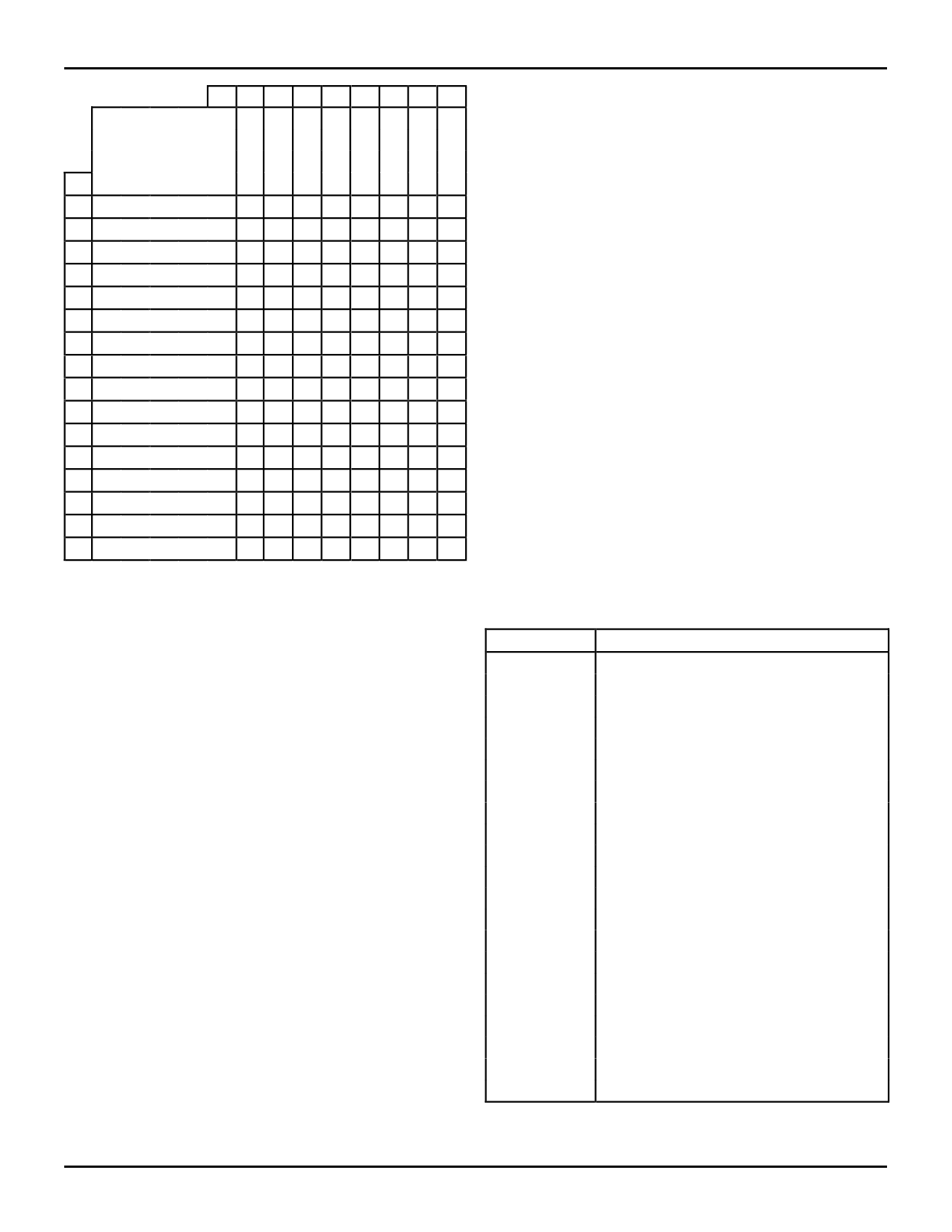
Syndrome
Bits
Hex 0 1 2 3 4 5 6 7
S6 0 0 0 0 1 1 1 1
S5 0 0 1 1 0 0 1 1
S4 0 1 0 1 0 1 0 1
Hex S3 S2 S1 S0
00 0 0 0
* C4 C5 T C6 T T 30
10 0 0 1
C0 T T 14 T M M T
20 0 1 0
C1 T T M T 2 24 T
30 0 1 1
T 18 8 T M T T M
40 1 0 0
C2 T T 15 T 3 25 T
50 1 0 1
T 19 9 T M T T 31
60 1 1 0
T 20 10 T M T T M
70 1 1 1
M T T M T 4 26 T
81 0 0 0
C3 T T M T 5 27 T
91 0 0 1
T 21 11 T M T T M
A1 0 1 0
T 22 12 T 1 T T M
B1 0 1 1
17 T T M T 6 28 T
C1 1 0 0
T 23 13 T M T T M
D1 1 0 1
M T T M T 7 29 T
E1 1 1 0
16 T T M T M M T
F1 1 1 1
TMM T 0 T T M
NOTES:
1. * = No errors detected
2. Number = The number of the single bit-in-error
3. T = Two errors detected
4. M = Three or more errors detected
2584 tbl 08
Table 7. Syndrome Decode to Bit-in-Error (32-Bit)
64-BIT DATA WORD CONFIGURATION
Two IDT49C460 EDC units, connected as shown in Figure
2, provide all the logic needed for single bit error detection and
double bit error detection of a 64-bit data field. Table 4 gives
the CODE ID1,0 values needed for distinguishing the upper 32
bits from the lower 32 bits. Valid syndrome, check bits and the
ERROR and MULT ERROR signals come from the IC with the
CODE ID1,0 = 11. Control signals not indicated are connected
to both units in parallel. The EDC with the CODE ID1,0 = 10
has the OESC grounded. The OESC selects the syndrome bits
from the EDC with CODE ID1,0 = 11 and also controls the
check bit buffers from memory.
Data In bits 0 through 31 are connected to the same
numbered inputs of the EDC unit with CODE ID1,0 = 10, while
Data In bits 32 through 63 are connected to Data Inputs 0 to
31, respectively, for the EDC unit with CODE ID1,0 = 11.
Figure 4 indicates the 72-bit data format of 8 bytes of data
and 8 check bits. Check bits are input to the EDC unit with
CODE ID1,0 = 10 through a three-state buffer unit such as the
IDT74FCT244. Correction of single bit errors of the 64-bit
configuration requires a feedback of syndrome bits from the
upper EDC unit to the lower EDC unit. The MUX shown on the
functional block diagram is used to select the CB0–7 pins as
the syndrome bits rather than internally generated syndrome
bits.
Table 3 describes the operating modes available for the 64/
72 configuration.
Table 11 indicates the data bits participating in the check bit
generation. For example, check bit C0 is the exclusive-OR
function of the 32 data input bits marked with an X. Check bits
are generated and output in the Generate and Initialization
modes. Check bits are passed as stored in the PASSTHRU or
Diagnostic Generate modes.
Syndrome bits are generated by an exclusive-OR of the
generated check bits with the read check bits. For example,
Sn is the XOR of check bits Cn from those read with those
generated. Table 9 indicates the decoding of the 8 syndrome
bits to determine the bit in error for a single bit error or whether
a double or triple bit error was detected. The all zero case
indicates no errors detected.
In the Correct Mode, the syndrome bits are used to
complement (correct) single bit errors in the data bits. For
double or multiple error detection, the data available as input
to the Data Out Latch is not defined.
Tables 8A and 8B define the bit definition for the Diagnostic
Latch. As defined in Table 3, several modes will use the
Diagnostic Check Bits to determine syndrome bits or to pass
as check bits to the SC0–7 outputs. The Internal Mode sub-
stitutes the indicated bit position for the external control
signals.
Performance data is provided in Table 10, relating a single
IDT49C460 EDC with the two cascaded units of Figure 2. As
indicated, a summation of propagation delays is required from
the cascading arrangement of EDC units.
Bit
Internal Function
0
1
2
3
4
5
6
7
8
9
10
11
12
13–31
32–39
40
41
42
43
44
45–63
CB0 DIAGNOSTIC
CB1 DIAGNOSTIC
CB2 DIAGNOSTIC
CB3 DIAGNOSTIC
CB4 DIAGNOSTIC
CB5 DIAGNOSTIC
CB6 DIAGNOSTIC
CB7 DIAGNOSTIC
CODE ID0 LOWER 32-BIT
CODE ID1 LOWER 32-BIT
DIAG MODE0 LOWER 32-BIT
DIAG MODE1 LOWER 32-BIT
CORRECT LOWER 32-BIT
DON'T CARE
DON'T CARE
CODE ID0 UPPER 32-BIT
CODE ID1 UPPER 32-BIT
DIAG MODE0 UPPER 32-BIT
DIAG MODE1 UPPER 32-BIT
CORRECT UPPER 32-BIT
DON'T CARE
2584 tbl 09
Table 8A. 64-Bit Diagnostic Latch–Coding Format
(Diagnostic and Correct Mode)
11.6
10
Share Link: 