IDT49C460 データシートの表示(PDF) - Integrated Device Technology
部品番号
コンポーネント説明
メーカー
IDT49C460 Datasheet PDF : 32 Pages
| |||
IDT49C460/A/B/C/D/E
32-BIT CMOS ERROR DETECTION AND CORRECTION UNIT
MILITARY AND COMMERCIAL TEMPERATURE RANGES
DETAILED PRODUCT DESCRIPTION
The IDT49C460 EDC units contain the logic necessary to
generate check bits on 32 bits of data input according to a
modified Hamming Code. The EDC can compare internally
generated check bits against those read with the 32-bit data
to allow correction of any single bit data error and detection of
all double (and some triple) bit errors. The IDT49C460s can
be used for 32-bit data words (7 check bits) and 64-bit (8 check
bits) data words.
WORD SIZE SELECTION
The two code identification pins, CODE ID1, 0, are used to
determine the data word size that is 32 or 64 bits. They also
select the Internal Control Mode. Table 4 defines all possible
slice identification codes.
CHECK AND SYNDROME BITS
The IDT49C460s provide either check bits or syndrome
bits on the three-state output pins, SC0–7. Check bits are
generated from a combination of the Data Input bits, while
syndrome bits are an exclusive-OR of the check bits gener-
ated from read data with the read check bits stored with the
data. Syndrome bits can be decoded to determine the single
bit in error or that a double (some triple) error was detected.
The check bits are labeled:
C0, C1, C2, C3, C4, C5, C6
for the 32-bit configuration
C0, C1, C2, C3, C4, C5, C6, C7 for the 64-bit configuration
Syndrome bits are similarly labeled S0 through S7.
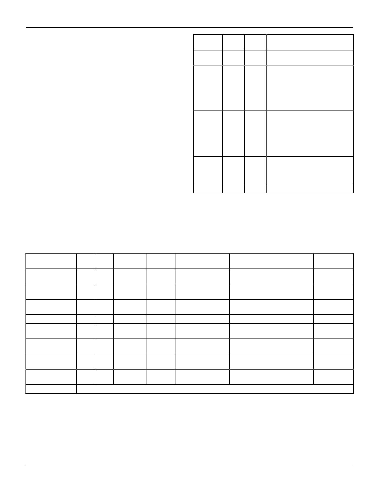
Correct
X
X
0/1
1
0
Diag Diag
Mode0 Mode1
Diagnostic Mode Selected
0
0 Non-diagnostic Mode. Normal
EDC function in this mode.
0
1 Diagnostic Generate. The con
tents of the Diagnostic Latch are
substituted for the normally
generated check bits when in the
Generate Mode. The EDC
functions normally in the Detect or
Correct modes.
1
0 Diagnostic Detect/Correct. In
either mode, the contents of the
Diagnostic Latch are substituted
for the check bits normally read
from the Check Bit Input Latch.
The EDC functions normally in the
Generate Mode.
1
1 Initialize. The Data Input Latch
outputs are forced to zeros and
latched upon removal of Initialize
Mode.
1
1 PASSTHRU.
2584 tbl 02
Table 2. Diagnostic Mode Control
Operating
Mode
Generate
Detect
DM0
0
1
0
0
DM1
0
0
0
1
Generate
0
1
Correct
X
0
DATAOUT Latch
LEOUT = LOW (1)
DATAIN Latch
SC0–7
(OESC = LOW)
Check Bits Generated from
DATAIN Latch
Syndrome Bits DATAIN/
Check Bit Latch
ERROR
MULT ERROR
High
Error Dep (2)
Correct
0
0
1
0
1
1
DATAIN Latch w/
Syndrome Bits DATAIN/
Single Bit Correction
Check Bit Latch
Error Dep
PASSTHRU
1
1
1
0
DATAIN Latch
Check Bit Latch
High
Diagnostic
Generate
0
1
0
X
—
Check Bits from Diagnostic Latch
High
Diagnostic Detect
1
0
1
0
DATAIN Latch
Syndrome Bits DATAIN/
Error Dep
Diagnostic Latch
Diagnostic Correct 1
0
1
1
DATAIN Latch w/
Syndrome Bits DATAIN/
Single Bit Correction
Diagnostic Latch
Error Dep
Initialization
1
1
1
1
DATAIN Latch
—
—
Set to 0000(3)
Internal
CODE ID1,0 = 01 (Control Signals CODE ID1,0, DIAG MODE1,0 and CORRECT are taken from Diagnostic Latch.)
NOTES:
2584 tbl 03
1. In Generate Mode, data is read into the EDC unit and the check bits are generated. The same data is written to memory along with the check bits. Since
the DATAOUT Latch is not used in the Generate Mode, LEOUT (being LOW since it is tied to Generate) does not affect the writing of check bits.
2. Error Dep (Error Dependent): ERROR will be low for single or multiple errors, with MULT ERROR low for double or multiple errors. Both signals are high
for no errors.
3. LEIN is LOW.
Table 3. IDT49C460 Operating Modes
11.6
7
Share Link: 