AD9802 データシートの表示(PDF) - Analog Devices
部品番号
コンポーネント説明
メーカー
AD9802 Datasheet PDF : 20 Pages
| |||
droop specifications needed. A capacitor value of 0.01 µF will
0
result in a droop of less than 10 LSB across one video line, and
requires only a CLAMP pulse of 1 µs to charge up. A larger
capacitor may be used to reduce droop, but then a longer
CLAMP pulse may be necessary.
AD9802
1V p-p
CIN
ADCIN
CLAMP
500⍀
SD210
CML
SHABYP
SHA
VRT
AD8047
OBSOLETE 500⍀
+3V
VRB
AD9802
ADCMODE
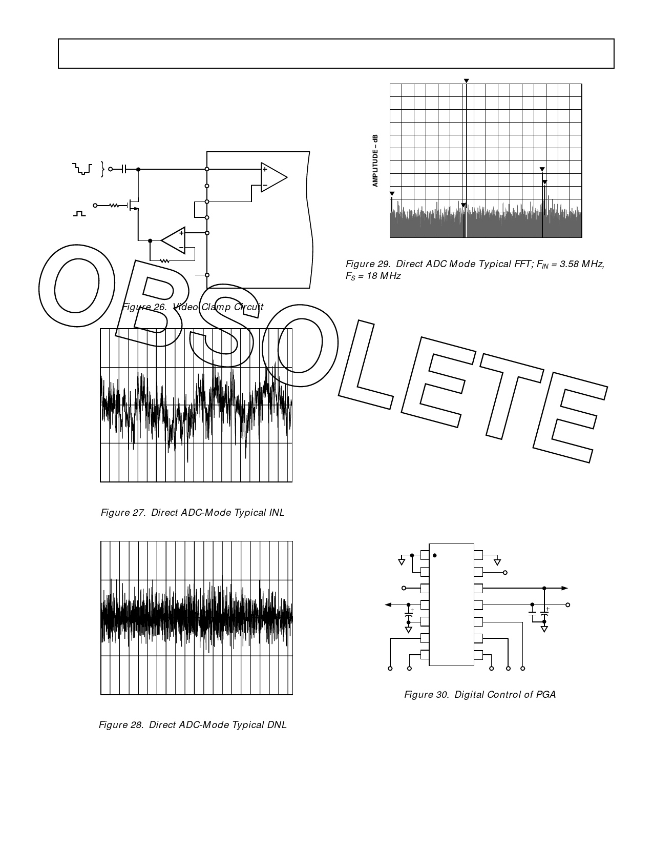
Figure 26. Video Clamp Circuit
1.0
0.5
0
–100
0
9.0
FREQUENCY – MHz
Figure 29. Direct ADC Mode Typical FFT; FIN = 3.58 MHz,
FS = 18 MHz
Figures 27–29 show the typical linearity and distortion perfor-
mance of the AD9802 in direct ADC mode.
Digitally Programmable Gain Control
The AD9802’s PGA is controlled by an analog input voltage of
0.3 V to 2.7 V. In some applications, digital gain control is
preferable. Figure 30 shows a circuit using Analog Devices’
AD8402 Digital Potentiometer to generate the PGA control
voltage. The AD8402 functions as two individual potentiom-
eters, with a serial digital interface to program the position of
each wiper over 256 positions. The device will operate with 3 V
or 5 V supplies, and features a power-down mode and a reset
function.
؊0.5
To keep external components to a minimum, the ends of the
“potentiometers” can be tied to ground and +3 V. One pot is
used for the coarse gain adjust, PGACONT1, with steps of
؊1.0
0 100 200 300 400 500 600 700 800 900 1023
about 0.2 dB/LSB. The other pot is used for fine gain control,
PGACONT2, and is capable of around 0.01 dB steps if all
eight bits are used. The two outputs should be filtered with
Figure 27. Direct ADC-Mode Typical INL
1 µF or larger capacitors to minimize noise into the PGACONT
pins of the AD9802.
1.0
1
14
2
13
+3V
0.5
+3V
3
12
PGACONT1
AD8402-10
PGACONT2
4
11
+3V
0
1F
5
0.1F
1F
10
6
9
؊0.5
7
8
SHDN CS
SDI CLK RS
؊1.0
0 100 200 300 400 500 600 700 800 900 1023
Figure 30. Digital Control of PGA
Figure 28. Direct ADC-Mode Typical DNL
REV. 0
–11–
Share Link: 