P89LPC932A1 データシートの表示(PDF) - NXP Semiconductors.
部品番号
コンポーネント説明
メーカー
P89LPC932A1
NXP Semiconductors.

P89LPC932A1 Datasheet PDF : 64 Pages
| |||
NXP Semiconductors
P89LPC932A1
8-bit microcontroller with accelerated two-clock 80C51 core
In edge-triggered mode, if successive samples of the INTn pin show a HIGH in one cycle
and a LOW in the next cycle, the interrupt request flag IEn in TCON is set, causing an
interrupt request.
If an external interrupt is enabled when the P89LPC932A1 is put into Power-down or Idle
mode, the interrupt will cause the processor to wake-up and resume operation. Refer to
Section 7.15 “Power reduction modes” for details.
RTCF
ERTC
(RTCCON.1)
WDOVF
IE0
EX0
IE1
EX1
BOF
EBO
KBIF
EKBI
EWDRT
CMF2
CMF1
EC
EA (IE0.7)
TF0
ET0
TF1
ET1
TI & RI/RI
ES/ESR
TI
EST
SI
EI2C
SPIF
ESPI
any CCU interrupt(1)
ECCU
EEIF
EIEE
(1) See Section 7.19 “CCU”
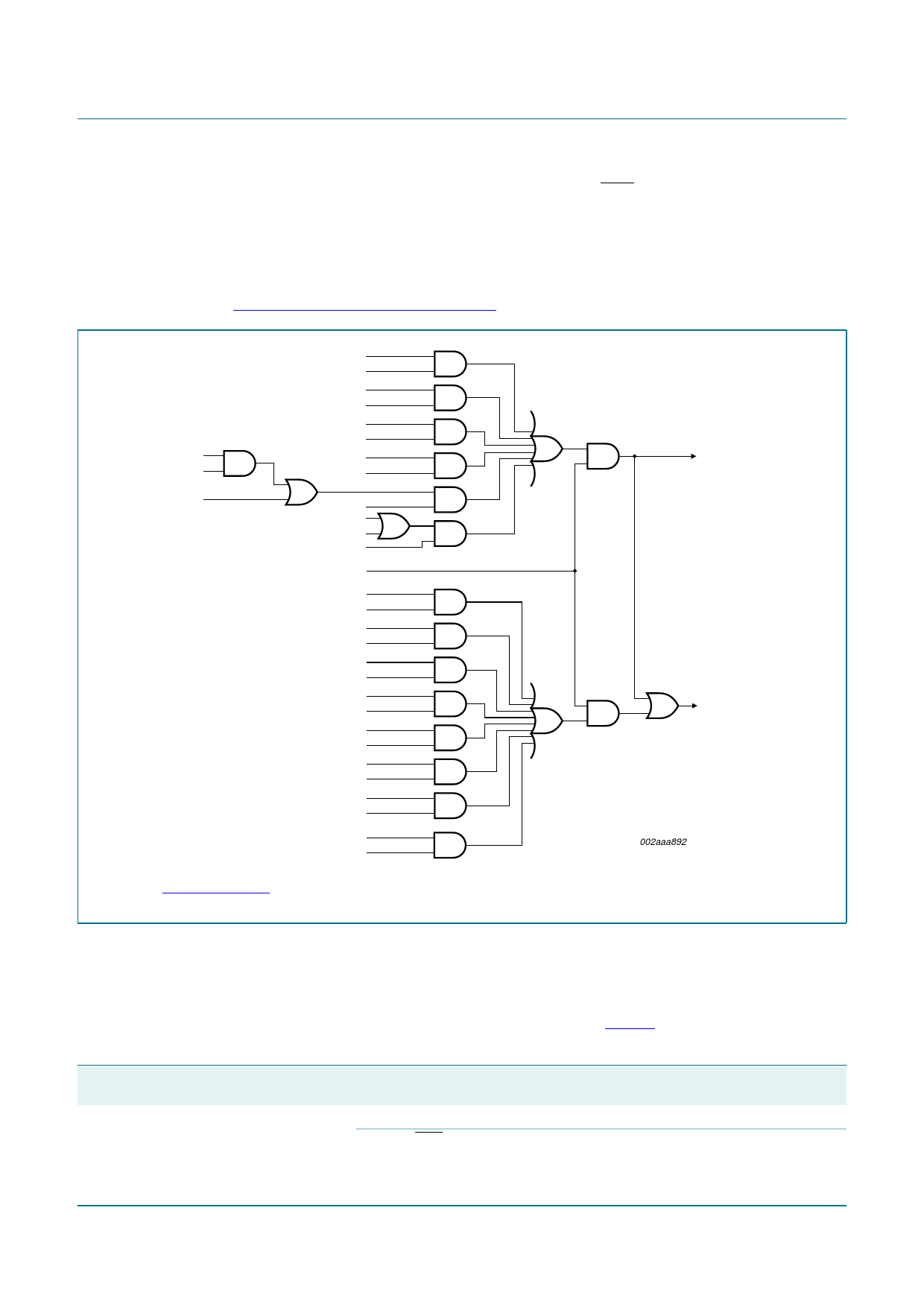
Fig 8. Interrupt sources, interrupt enables, and power-down wake-up sources
wake-up
(if in power-down)
interrupt
to CPU
002aaa892
7.13 I/O ports
The P89LPC932A1 has four I/O ports: Port 0, Port 1, Port 2, and Port 3. Ports 0, 1 and 2
are 8-bit ports, and Port 3 is a 2-bit port. The exact number of I/O pins available depends
upon the clock and reset options chosen, as shown in Table 5.
Table 5. Number of I/O pins available
Clock source
Reset option
On-chip oscillator or watchdog oscillator
No external reset (except during power-up)
External RST pin supported
Number of I/O pins
(28-pin package)
26
25
P89LPC932A1_3
Product data sheet
Rev. 03 — 12 March 2007
© NXP B.V. 2007. All rights reserved.
21 of 64
Share Link: