AN87C196CA18 データシートの表示(PDF) - Intel
部品番号
コンポーネント説明
メーカー
AN87C196CA18 Datasheet PDF : 30 Pages
| |||

Automotive — 87C196CA 18 MHz Microcontroller
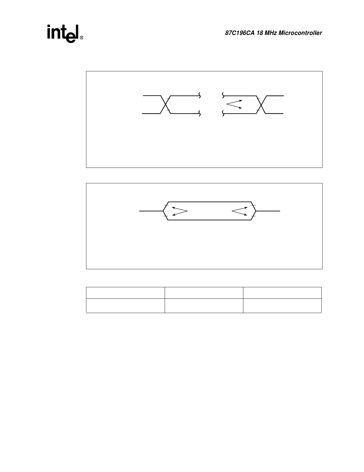
Figure 8. AC Testing Input, Output Waveforms
INPUTS
3.5 V
0.45 V
Test Points
OUTPUTS
2.0 V
0.8 V
Note:
AC testing inputs are driven at 3.5 V for a logic “ 1” and 0.45 V for a logic
“ 0” . Timing measurements are made at 2.0 V for a logic “ 1” and 0.8 V for
a logic “ 0”.
A4651-01
Figure 9. Float Waveforms
VLOAD + 0.15 V
VLOAD
VLOAD – 0.15 V
Timing Reference
Points
VOH – 0.15 V
VOL + 0.15 V
Note:
For timing purposes, a port pin is no longer floating when a 150 mV change from load
voltage occurs and begins to float when a 150 mV change from the loading VOH/VOL
level occurs with IOL/IOH ≤ 15 mA.
A5844-01
Table 8.
Thermal Characteristics
Device and Package
θJA
θJC
AN87C196CA
(68-Lead PLCC)
36.5°C/W
10°C/W
NOTES:
1. θJA = Thermal resistance between junction and the surrounding environment (ambient). Measurements are
taken 1 ft. away from case in air flow environment.
θJC = Thermal resistance between junction and package surface (case).
2. All values of θJA and θJC may fluctuate depending on the environment (with or without airflow, and how
much airflow) and device power dissipation at temperature of operation. Typical variations are ±2°C/W.
3. Values listed are at a maximum power dissipation of 0.50 W.
Datasheet
15