TFRA08C13 データシートの表示(PDF) - Agere -> LSI Corporation
部品番号
コンポーネント説明
メーカー
TFRA08C13 Datasheet PDF : 188 Pages
| |||
TFRA08C13 OCTAL T1/E1 Framer
Preliminary Data Sheet
October 2000
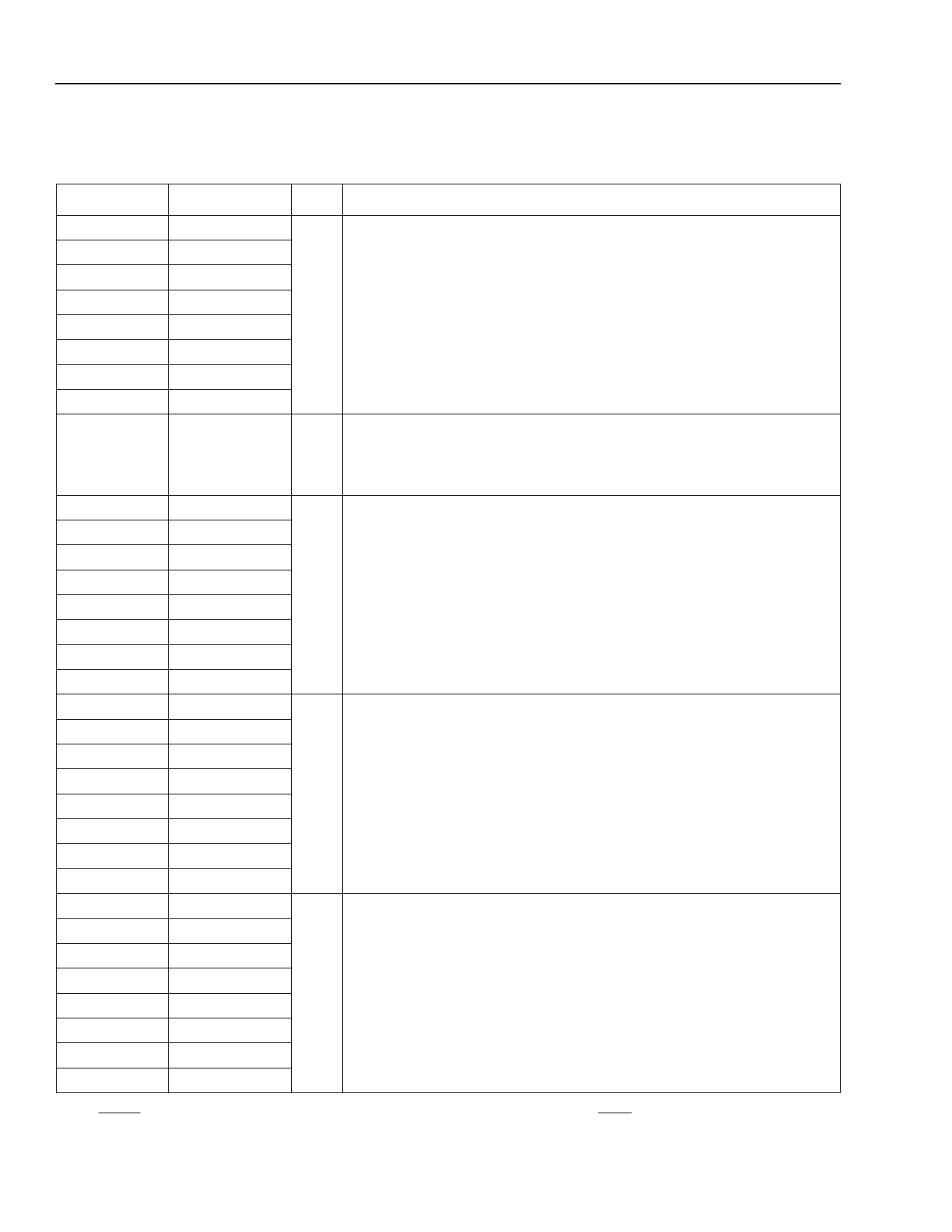
Pin Information (continued)
Table 2. Pin Descriptions (continued)
Pins
Symbol Type*
Description
D5
L1
V3
AC10
W26
K23
PLLCK[1]
PLLCK[2]
PLLCK[3]
PLLCK[4]
PLLCK[5]
PLLCK[6]
I Transmit Framer Phase-Locked Line Interface Clock. Clock signal
used to time the transmit framer. This signal must be phase-locked to
CHICK clock signal. In DS1 frame formats, PLLCK can be a low-
frequency signal (1.544 MHz) or a high frequency signal (6.176 MHz).
In CEPT frame formats, PLLCK can be a low-frequency signal
(2.048 MHz) or a high-frequency signal (8.192 MHz).
A20
PLLCK[7]
D7
PLLCK[8]
F25
LOPLLCK
O Loss of PLLCK Clock. This pin is asserted high when the PLLCK
clock does not toggle for a 250 µs interval. This pin is deasserted
250 µs after the first edge of PLLCK (see Table 66. Global Control Reg-
ister (GREG8) (008)).
F1
TLCK[1]
O Transmit Framer Line Interface Clock. Optional 1.544 MHz DS1 or
R4
TLCK[2]
AE3
TLCK[3]
2.048 MHz output signal from the transmit framer. TND and TPD data
changes on the rising edge of TLCK.
AF19
AE26
R26
TLCK[4]
TLCK[5]
TLCK[6]
E23
C12
G1
U1
AD4
AC19
TLCK[7]
TLCK[8]
TPD[1]
TPD[2]
TPD[3]
TPD[4]
O Transmit Line Interface Positive-Rail Data. This signal is the transmit
framer positive NRZ output data. Data changes on the rising edge of
TLCK. In the single-rail mode, TPD = transmit framer data.
AE22
TPD[5]
T26
TPD[6]
E25
TPD[7]
A12
TPD[8]
G2
TND[1]
O Transmit Line Interface Negative-Rail Data. This signal is the trans-
U2
TND[2]
AE4
TND[3]
mit framer negative NRZ output data. Data changes on the rising edge
of TLCK. In the single-rail mode, TND = 0.
AE20
AF22
R25
TND[4]
TND[5]
TND[6]
E26
TND[7]
B11
TND[8]
* Iu indicates an internal pull-up, Id indicates an internal pull-down.
† After RESET is deasserted, the channel is in the default framing mode, as a function of the DS1/CEPT pin.
‡ Asserting this pin low will initially force RDY to a low state.
20
LuLcuecnetnTteTcehcnhonloolgoigeisesInIcn.c.
Share Link: 