M65676FP データシートの表示(PDF) - MITSUBISHI ELECTRIC
部品番号
コンポーネント説明
メーカー
M65676FP Datasheet PDF : 17 Pages
| |||
PRELIMINARY
Notice:This is not a final specification.
Some parametric limits are subject to change.
MITSUBISHI ICs (TV)
M65675FP/M65676FP
DIGITAL NTSC/PAL ENCODER
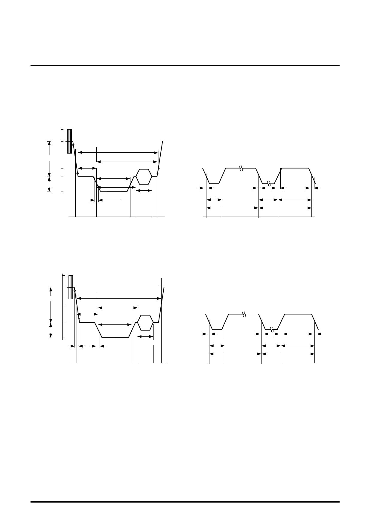
Composite-sync Generation
The timing-corrected c-sync signal, for an addition to the Y signal, is
generated in accordance with RS170A (NTSC) and CCIR (PAL)
standards, as shown in fig. 4.
IRE
133
100
90
0.714V
20
4
0
0.286V
-40
peak level including chroma signal
white peak level
0H(reference point)
10.9±0.2µs
1.5±0.1µs
9.4±0.1µs
4.7±0.1µs
40
±2
19 cycles
0.14±0.1µs
9 cycles
Equalizing pulse
Serrated pulse
set-up
7.5±2
0.14±0.2µs
0.14±0.2µs
0.14±0.2µs
2.3±0.1µs
31.7775µs
27.1µs 4.7±0.1µs
31.7775µs
0.14±0.2µs
837
0
858
cycle counts (13.5MHz)
63 72 106127
0
31
429 460
cycle counts (13.5MHz)
0
366
429
795
Fig. 4-1 NTSC HORIZONTAL SYNC SIGNAL (referred to EIARS170A)
IRE
133
peak level including chroma signal
100
90
0.7V
50
10
0
0.3V
-43
0.3±0.1µs
white peak level
0H(reference point)
12±0.3µs
1.5±0.3µs
5.6±0.1µs
4.7±0.2µs
43
±10%
set-up
0-2
0.2±0.1µs
0.2±0.1µs
10±1cycles
Equalizing pulse
Serrated pulse
0.2±0.1µs
0.2±0.1µs
2.35±0.1µs
62.0µs
27.3µs 4.7±0.2µs
62.0µs
0.2±0.1µs
844
0
864
cycle counts (13.5MHz)
63 76 107142
0
32
432 464
cycle counts (13.5MHz)
0
368
432
800
Fig. 4-2 PAL HORIZONTAL SYNC SIGNAL (referred to CCIR)
Serial Interface
The M65675FP/M65676FP has a serial data receiver, in
compliance with both typical and high speed modes, based on I2C
serial bus specification. The slave-address of it also responds to
two addresses of 40h and 42h. The address setting is done by
following procedure;
address setting pin DVASEL (pin 3) is "L" and "H" for the address of
40h and 42h, respectively.
The serial data are stored in the data register in the serial interface
block according to the appointed address after the receipt of the
data. The stored data will be loaded to the registers in each internal
blocks at the timing of the first trailing edge of V-sync after the
transmission flag (WE) have been set up.
Analog Blocks
D-A Converter
The M65675FP/M65676FP has two 10-bit D-A converters. A
reference current of the D-A converters is supplied directly through
the Yref and Cref pins. The power save mode cuts the circuit
current. The maximum output amplitude is 1.2VP-P.
9
Share Link: 