FSFR1800HSL データシートの表示(PDF) - Unspecified
部品番号
コンポーネント説明
メーカー
FSFR1800HSL Datasheet PDF : 16 Pages
| |||
The initial maximum frequency can be set up to 600 kHz,
which is given by:
f ss
=
1
792 p × Rmin || RSS + 0.54μ
[ Hz ]
(3)
The soft-start time, tSS, can be calculated by:
tSS = 3 × RSS ⋅ CSS [ s ]
(4)
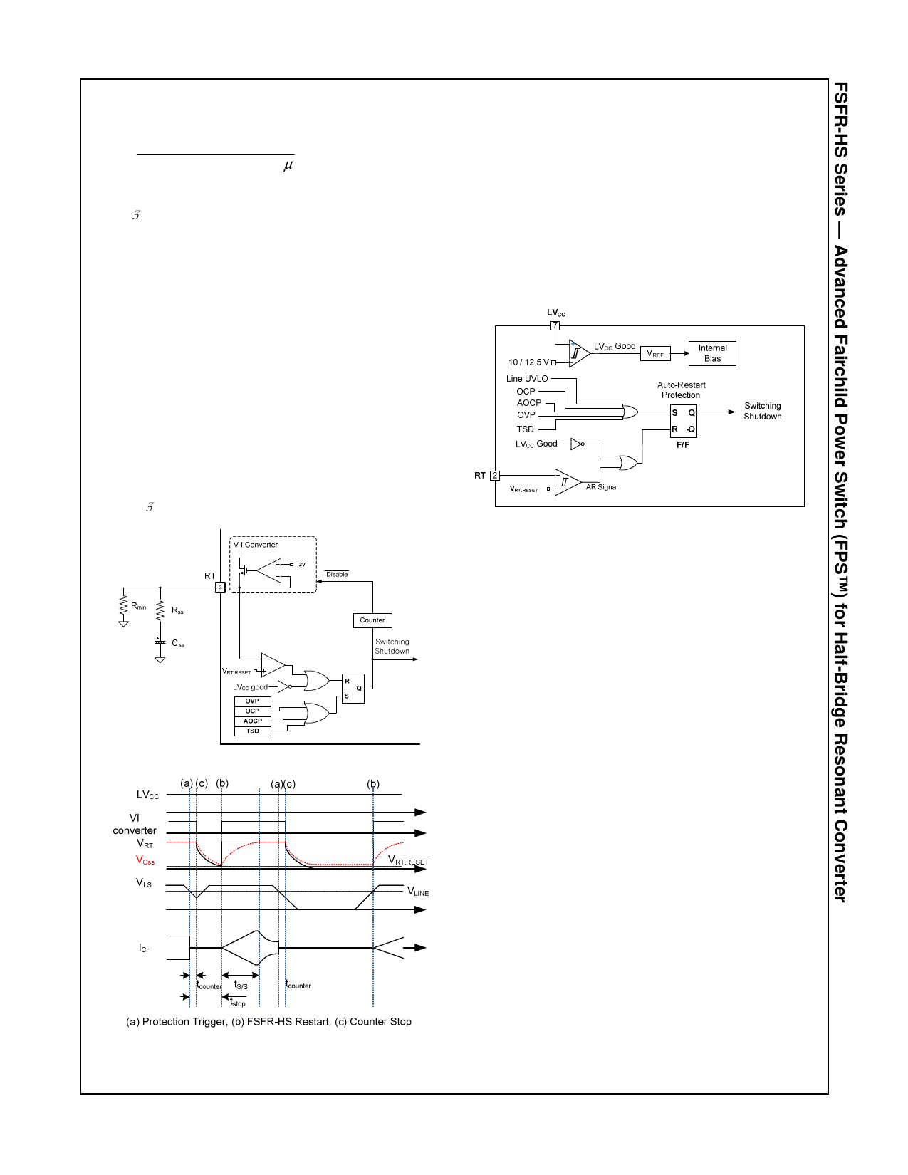
4. Self Auto-Restart: The FSFR-HS series can restart
automatically even though any built-in protections are
triggered in case external supply voltage is applied. As
shown in Figure 22 and Figure 23; once a protection is
triggered, the power MOSFET immediately stops. The
counter starts to operate and 1008-clocks are counted,
then the V-I converter is disabled. CSS starts to be naturally
discharged with the series impedance of RSS and Rmin until
VRT drops to VRT,RESET, typically 0.1 V. Then, all protections
are reset and the V-I converter resumes. The FSFR-HS
starts switching again with soft-start.
The counter operating time for 1008-clocks after
protection activation is set by the current out of the RT
pin until VRT drops to VRT,RESET. Finally, the stop time of
FSFR-HS can be estimated, without considering the
counter operation time, as:
tSTOP = 3 CSS ⋅ (RSS + Rmin ) [ s ]
(5)
Figure 22. Internal Block for Auto-Restart
Figure 23. Self Auto-Restart Operation
5. Protection Circuits: The FSFR-HS series has several
self-protective functions; such as Over-Current Protection
(OCP), Abnormal Over-Current Protection (AOCP), Over-
Voltage Protection (OVP), Thermal Shutdown (TSD), and
Line Under-Voltage Lockout (LUVLO or Brownout).
These protections are Auto-Restart Mode protections, as
shown in Figure 24.
Once a fault condition is detected, switching is instantly
terminated and the MOSFETs remain off. When LVCC falls
to the LVCC stop voltage of 10 V and VRT is lower than
VRT,RESET of 0.1 V, the protection is reset. The FSFR-HS
resumes normal operation when LVCC reaches the start
voltage of 12.5 V.
Figure 24. Protection Blocks
5.1 Over-Current Protection (OCP): When the
sensing pin voltage drops below -0.58 V and its
duration becomes more than OCP blanking time of
1.5 µs, OCP is triggered and the MOSFETs remain off.
5.2 Abnormal Over-Current Protection (AOCP):
If the secondary rectifier diodes are shorted, large
current with extremely high di/dt can flow through the
MOSFET before OCP is triggered. AOCP is triggered
without shutdown delay if the sensing pin voltage drops
below -0.9 V.
5.3 Over-Voltage Protection (OVP): When the LVCC
reaches 23 V, OVP is triggered. This protection is used
when auxiliary winding of the transformer supplies VCC
to the FPS™.
5.4 Thermal Shutdown (TSD): The MOSFETs and
the control IC in one package make it easier for the
control IC to detect the abnormal over-temperature of
the MOSFETs. If the temperature exceeds
approximately 130°C, thermal shutdown triggers.
6. Line Under-Voltage Lockout (UVLO): FSFR-HS
includes precise line UVLO (or brownout) with
programmable hysteresis voltage. This function can start
or restart the IC when VLS for the scale-down voltage of
the DC-link by the sensing resistors, R1 and R2, is higher
than VLINE of 2.5 V as the DC-link voltage increases and
vice versa. A hysteresis voltage between the start and
stop voltage of the IC is programmable by ILINE. In normal
operation, the comparator’s output is HIGH and ILINE is
deactivated so that a voltage on LS pin, VLS, can be
obtained as a divided voltage by R1 and R2. On the
contrary, ILINE is activated when the comparator’s output
is LOW. VLS is generated by the difference between the
current through R1 and ILINE.
© 2011 Fairchild Semiconductor Corporation
FSFR1800 / FSFR1700-HS • Rev.1.0.1
11
www.fairchildsemi.com
Share Link: 